Drive circuit for light emitting diode

a technology of driving circuit and light-emitting diodes, which is applied in the direction of identification means, instruments, lighting and heating apparatus, etc., can solve the problems of reducing the voltage of emitting light, wasting time and labor to find defective led bulbs, and producing white light that is not uniform, so as to reduce the driving voltage and produce luminance more stable

Active Publication Date: 2008-07-03
MACROBLOCK INC
View PDF8 Cites 20 Cited by
  • Summary
  • Abstract
  • Description
  • Claims
  • Application Information

AI Technical Summary

Benefits of technology

[0012]When the string voltage is higher than the reference voltage, the power converter raises the driving voltage to drive the LED strings to emit light; and when the string voltage is lower than the reference voltage, the power converter reduces the driving voltage. Thereby, a constant voltage drop exists between the driving voltage and the forward bias of the LEDs, such that the drive circuit provides the same voltage to the LED strings for emitting light, and thus the produced luminance is more stable.

Problems solved by technology

However, after the display is used for a long time, the luminance of one LED bulb in the lamp set of a certain color often becomes insufficient, which causes non-uniform luminance in the white light produced through the mixture of the R, G, and B lights of the entire color light lamp sets.
Since the LED light lamp set is usually a modulated product, it is a waste of time and labor to find the defective LED bulb from so many LED bulbs.
On the contrary, if the forward bias increases, the voltage applied on the driving IC (integrated circuitry) increases, the voltage for emitting light will decrease, and thus the produced brightness is lower, which is a challenge for the case requiring stable luminance.

Method used


Image

  • Drive circuit for light emitting diode
  • Drive circuit for light emitting diode
  • Drive circuit for light emitting diode

Examples


first embodiment

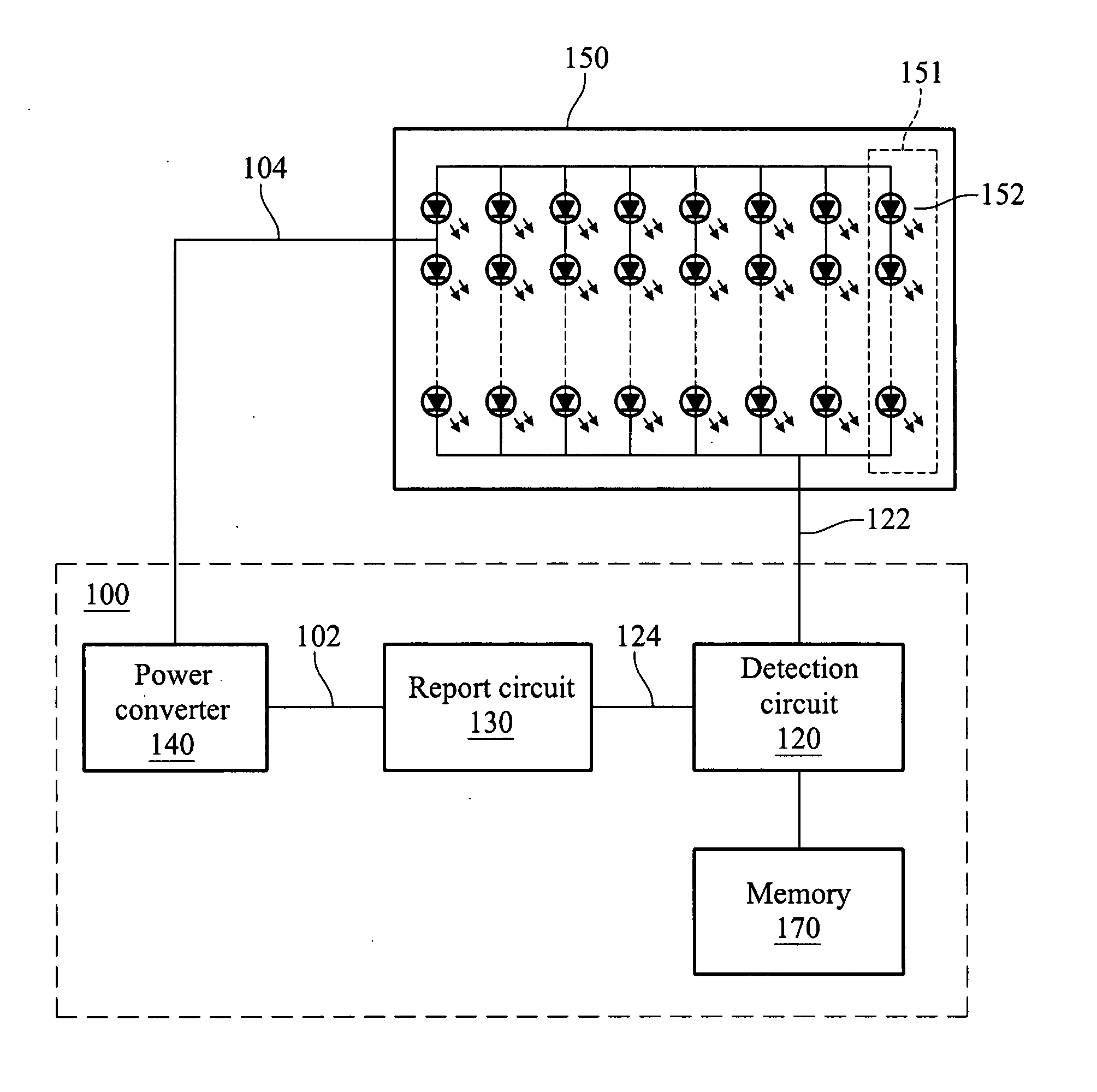
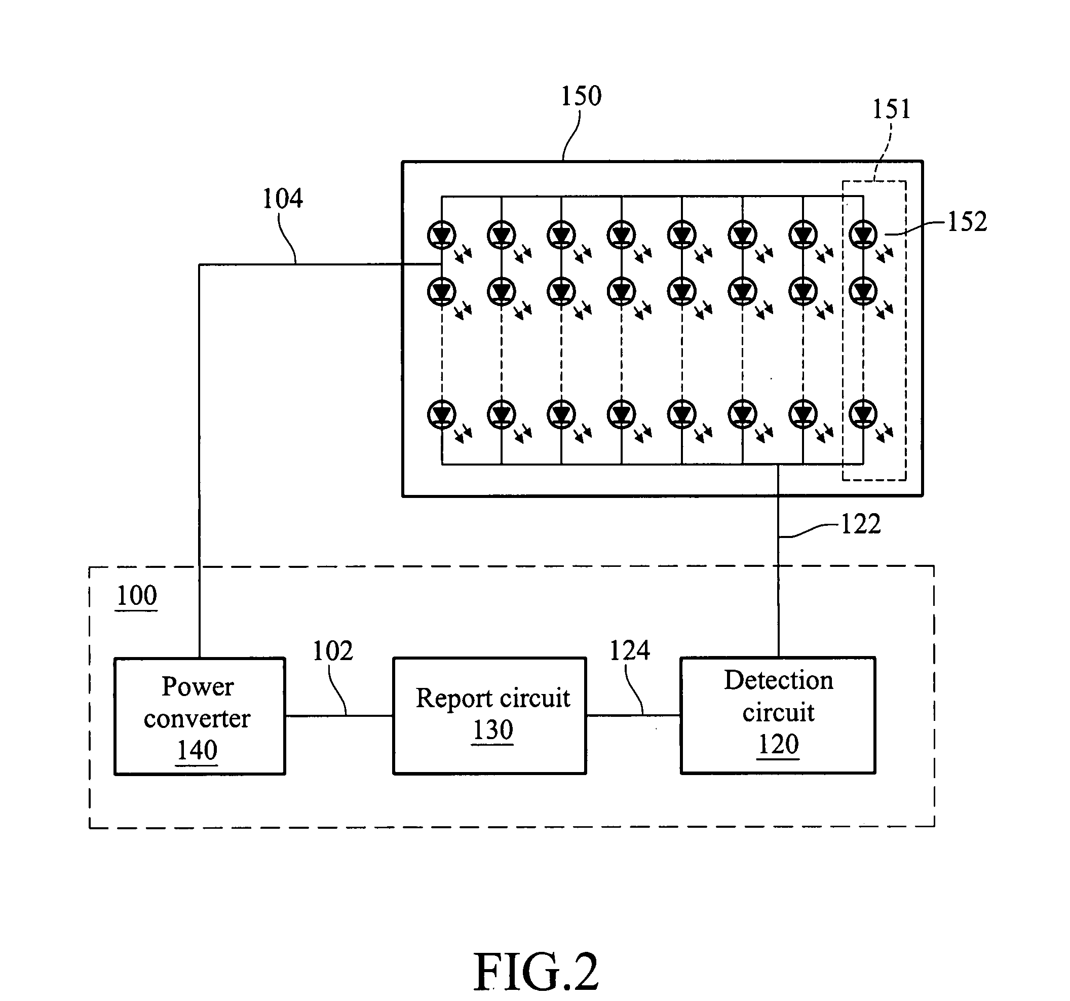
[0021]FIG. 2 is a circuit block diagram of the present invention. It can be found from FIG. 2 that the drive circuit 100 for LED of the present invention is used to drive an LED group 150 that includes a plurality of LED strings 151 connected in parallel (in FIG. 2, an LED group 150 includes eight LED strings 151). Each LED string 151 is includes a plurality of LEDs 152 connected in series. The drive circuit 100 drives the LED group 150 through providing a constant voltage or a constant current, and in the present invention, the drive circuit 100 uses a constant voltage to drive the LED group 150. The drive circuit 100 can drive all of the LED strings 151 at the same time, or can selectively drive a specific LED string 151 to emit light and drive each LED string 151 sequentially and repeatedly, such that the LED strings 151 are all driven. Meanwhile, if the switching speed is high enough, e.g., the switching time is less than 1 / 30 second, to human eyes, each LED 152 is constantly on...

second embodiment

[0031]Furthermore, FIG. 3 is a diagram of the present invention. It can be found from FIG. 3 that switch components 160 are corresponding to the LED strings 151, and the switch components 160 are electrically coupled to the LED group 150, the report circuit 130, and the detection circuit 120. The report circuit 130 selectively turns on one of the switch components 160, such that the power converter 140 drives the turned-on LED string 151 (the LED string 151 corresponding to the turned-on switch component 160). Thereby, only one LED string 151 is turned on at a same time point. In addition, the detection circuit 120 also only detects the string voltage 122 of the turned-on LED string 151, compares the string voltage 122 with the reference voltage, and outputs the detection signal 124 to the report circuit 130. The report circuit 130 then outputs the control signal 102 of the corresponding detection signal 124 to the power converter 140. The power converter 140 adjusts the driving vol...

third embodiment

[0036]Furthermore, FIG. 5 is a diagram of the present invention. It can be found from FIG. 5 that the detection circuit 120 is further electrically coupled to a memory 170, which stores the reference voltage of each LED string 151. Therefore, when the detection circuit 120 detects the string voltage 122 of a LED string 151, the reference voltage corresponding to the LED string 151 is obtained from the memory 170 for comparison, so as to output a detection signal. Thus, the above function can also be achieved. Moreover, the memory 170 can also be realized by using a variable resistor.

[0037]Finally, the reference voltage is compared when the detection circuit 120 detects the string voltage 122, so as to output a detection signal 124 to the report circuit 130. However, besides this method, the reference voltage also can be allocated at the report circuit 130. Thereby, the detection circuit 120 detects and outputs a string voltage 122 of the LED strings 151 respectively, and the report ...


PUM


Abstract

A drive circuit for light emitting diode (LED) is provided, which is used to drive a plurality of LEDs to emit light. The LEDs are connected in series into a plurality of LED strings. The drive circuit includes a power converter, a detection circuit, and a report circuit. The power converter provides a driving voltage to the LED strings, and the detection circuit detects a string voltage of each LED string, and compares the string voltage with a default reference voltage, so as to determine whether the string voltage is different from the reference voltage (which indicates that the LED string is operated under a non-default state), and sends a detection signal to the report circuit. The report circuit receives the detection signal and outputs the control signal to the power converter, such that the power converter adjusts the driving voltage according to the control signal.

Description

CROSS-REFERENCE TO RELATED APPLICATIONS[0001]This non-provisional application claims priority under 35 U.S.C. § 119(a) on Patent Application No(s). 095150085 filed in Taiwan, R.O.C. on Dec. 29, 2006, the entire contents of which are hereby incorporated by reference.BACKGROUND OF THE INVENTION[0002]1. Field of Invention[0003]The present invention relates to a drive circuit for light emitting diode (LED), and more particularly, to an LED drive circuit for driving and connecting a plurality of serially connected LED circuits in parallel.[0004]2. Related Art[0005]Light emitting diodes (LEDs) are widely used in daily life in recent years, such as in displays, household appliances, vehicle electronic components, and lighting lamps. Taking the displays as an example, a conventional display includes lamp sets of three-color lights, namely, a red (R) lamp set, a green (G) lamp set, and a blue (B) lamp set. Before the lamp sets of three-color lights are assembled, it shall be determined first...

Claims


Application Information

Patent Timeline
Patent Type & Authority Applications(United States)
IPC IPC(8): F21S4/00H01L33/00
CPCH05B33/0851H05B45/52G09F9/33G09G3/14H05B45/10
Inventor LIN, YI-SHENG
Owner MACROBLOCK INC
Why Eureka
Try Eureka