Sensors

a technology of sensors and sensors, applied in the field of sensors, can solve the problems of insignificantaffecting the performance of the sensor, and affecting the performance of the sensor, and achieving the effect of improving the optical performance of the device, reducing the cost of storage and transportation, and improving the accuracy of the sensor

Inactive Publication Date: 2008-07-03
SPECTALIS
View PDF9 Cites 33 Cited by
  • Summary
  • Abstract
  • Description
  • Claims
  • Application Information

AI Technical Summary

Benefits of technology

[0024]The strip may have a width much greater than its thickness, in which case the plasmon-polariton waveguide will be substantially polarization sensitive and the input optical radiation, preferably, linearly polarized. The coupling m

Problems solved by technology

Following this convention, dimensions in general that are said to be “optically infinite” or “optically semi-infinite” are so large that they are insignificant to the optical performance of the device.
The production, storage and transportation of hydrogen gas present certain problems

Method used


Image

  • Sensors
  • Sensors
  • Sensors

Examples


example 1

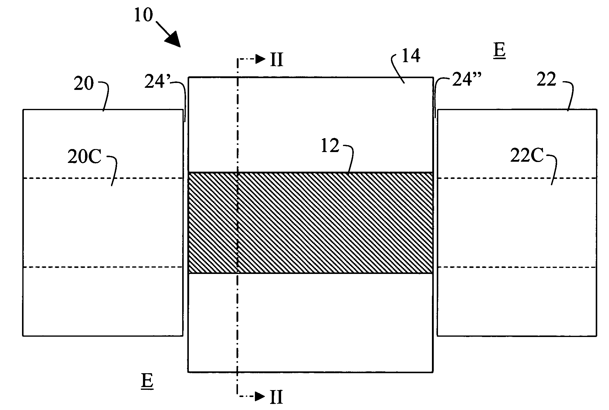
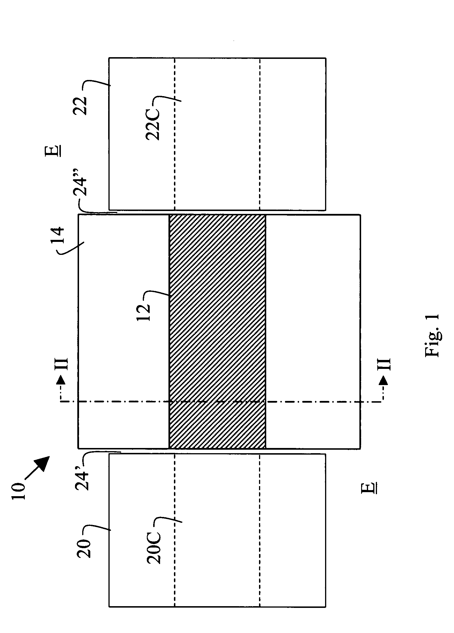
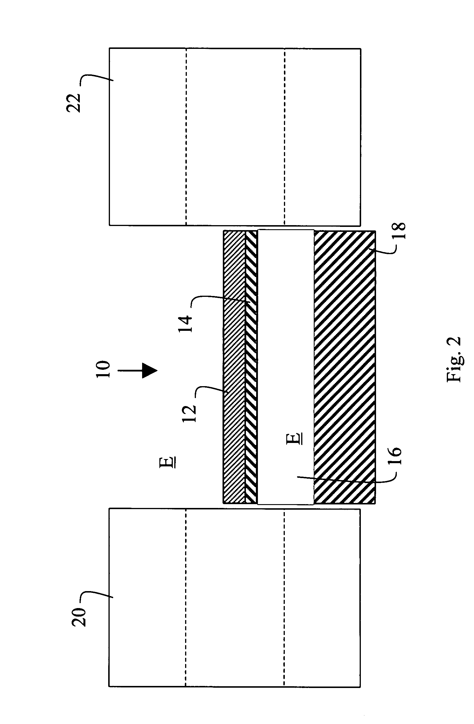
[0092]The free-space operating wavelength was set to 1550 nm, SiO2 (∈r,2=1.4442) was selected as the material of the membrane 14, Au (∈r,3=−131.95−j12.65) was selected as the material of the strip 12, and vacuum (∈r,1=1) was selected as the environment E. The width w of the strip 12 was set to 8 μm, its thickness t was set to 30 nm, and the thickness d of the membrane 14 was varied from substantially 0 to about 65 nm for the purpose of illustrating its impact on the performance of the waveguide.

[0093]FIG. 6 gives the computed effective refractive index β / β0 of the ssb0 mode over the range of membrane thicknesses d. The effective refractive index of the TE0 and TM0 modes supported by the membrane 14 alone (i.e.: without the strip 12) was also plotted for reference.

[0094]FIG. 7 gives the computed attenuation of the ssb0 mode over the range of membrane thickness d, showing that the attenuation increases slightly with membrane thickness—indicating increasing confinement to the strip 12....

example 2

[0097]The free-space operating wavelength was set to 1310 nm, SiO2 (∈r,2=1.44682) was selected as the material for the membrane 14, Au (∈r,3=−86.08−j8.322) was selected as the material for the strip 12, and vacuum (∈r,1=1) was selected for the environment E. The width w of the strip was set to 6 μm, its thickness t was set to 30 μm, and the thickness d of the membrane was varied from substantially 0 to about 55 nm for the purpose of illustrating its impact on the performance of the waveguide.

[0098]FIG. 9 gives the computed effective refractive index of the ssb0 mode over the range of membrane thickness. The effective index of the TE0 and TM0 modes supported by the membrane 14 alone (i.e.: without the strip 12) was also plotted for reference.

[0099]FIG. 10 gives the computed attenuation of the ssb0 mode over the range of membrane thicknesses d, showing that the attenuation increases slightly with membrane thickness—indicating increasing confinement to the strip 12. The attenuation rem...

example 3

[0102]The free-space operating wavelength was set to 632.8 nm, Si3N4 (∈r,2=2.02112) was selected as the material of the membrane 14, Au (∈r,3=−11.7851−j1.2562) was selected as the material of the strip 12, and vacuum (∈r,1=1) was selected for the environment E. The width w of the strip 12 was set to 0.95 μm, its thickness t was set to 25 nm, and the thickness d of the membrane 14 was set to 20 nm. The computed effective refractive index of the ssb0 mode was 1.00898, its attenuation was 4.39 dB / 100 μm and its coupling loss to standard single mode fiber was 1.60 dB. For reference, the effective index of the TE0 and TM0 modes supported by the membrane 14 alone (i.e., without the strip 12) are 1.04412 and 1.00285, respectively. FIG. 30(a) gives the computed distribution of Re{Ey} over the waveguide cross-section.

[0103]Thus, when the free-space operating wavelength is set to 632.8 nm, the membrane 14 to Si3N4, the strip 12 to Au, and the environment to vacuum, the dimensions w=0.95 μm, t...


PUM


Abstract

A gas sensor for hydrogen or other gases, especially flammable or explosive gases, has a plasmon-polariton waveguide comprising a metal strip on a membrane supported by a substrate in an environment in which the gas is to be introduced, and coupling means for coupling optical radiation into and out of the plasmon-polariton waveguide such that the optical radiation propagates therealong as a plasmon-polariton wave. The metal strip comprises by a chemical transducer (e.g. Pd or PdNi), the arrangement being such that exposure of the metal strip or coating to the gas to be monitored causes a change in the propagation characteristics of the plasmon-polariton wave and hence the optical radiation coupled out of the plasmon-polariton waveguide.

Description

CROSS-REFERENCE TO RELATED APPLICATION[0001]This application claims priority from U.S. Provisional patent application No. 60 / 838,861 filed Aug. 21, 2006, the contents of which are incorporated by reference.TECHNICAL FIELD[0002]The invention relates to sensors, particularly sensors for sensing gases, and is especially applicable to sensors for sensing flammable or explosive gases, such as hydrogen.BACKGROUND[0003]In the context of this patent specification:[0004]The term “optical radiation” embraces electromagnetic waves having wavelengths in the infrared, visible and ultraviolet ranges.[0005]The terms “finite” and “infinite” as used herein are used by persons skilled in this art to distinguish between waveguides having “finite” widths in which the actual width is significant to the performance of the waveguide and the physics governing its operation and so-called “infinite” waveguides where the width is so great that it has no significant effect upon the performance and physics of o...

Claims


Application Information

Patent Timeline
IPC IPC(8): G01N21/00
CPCG01N2021/7779G01N21/7703
Inventor BERINI, PIERRE SIMON JOSEPHCHARBONNEAU, ROBERTLAHOUD, NANCY
Owner SPECTALIS
Why Eureka
Try Eureka