Light guide plate

Inactive Publication Date: 2008-07-03
IND TECH RES INST
View PDF7 Cites 49 Cited by
  • Summary
  • Abstract
  • Description
  • Claims
  • Application Information

AI Technical Summary

Benefits of technology

[0007]The invention provides a light guide plate which has excellent light

Problems solved by technology

However, the conventional backlight module 100 needs to utilize a plurality of optical films, and cost of these f

Method used


Image

  • Light guide plate
  • Light guide plate
  • Light guide plate

Examples


Example

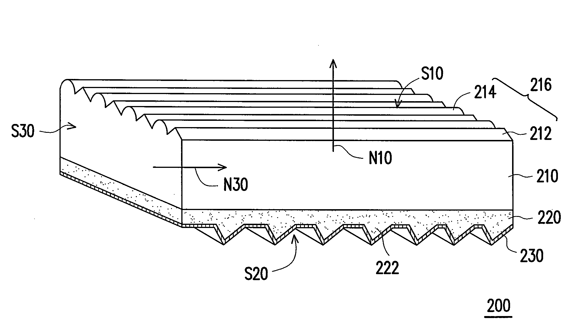
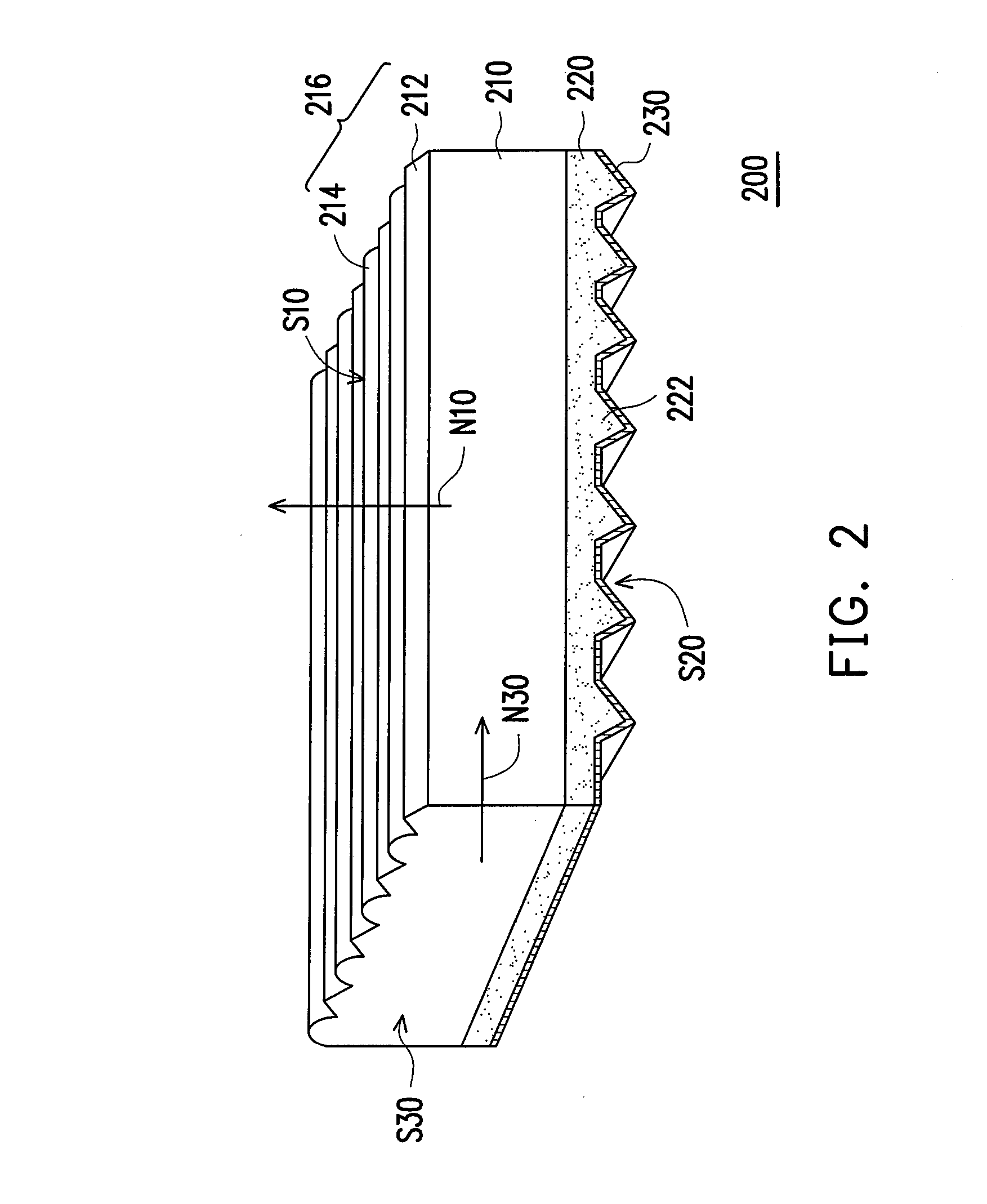
[0016]FIG. 2 is a perspective view of a light guide plate according to an embodiment of the present invention. Referring to FIG. 2, the light guide plate 200 has a light emitting surface S10, a bottom surface S20 and at least one light incident surface S30 connected with the light emitting surface S10 and the bottom surface S20. The light guide plate 200 is formed with a plurality of laminated material layers (two material layers 210 and 220 shown in this embodiment). Each of the material layers 210, 220 is substantially parallel to the light emitting surface S10. That is, the portion of the light guide plate 200 adjacent to the light emitting surface S10 is formed with one material (e.g., the material layer 210), and the portion of the light guide plate 200 adjacent to the bottom surface S20 is formed with another material (e.g., the material layer 220).

[0017]Generally, the light emitting surface S10 and the bottom surface S20 of the light guide plate 200 both have stripe-shaped mi...


PUM


Abstract

A light guide plate with a light emitting surface, a bottom surface and at least one light incident surface being connected with the light emitting surface and the bottom surface is provided. The light guide plate is a superposition of a plurality of layers substantially parallel to the light emitting surface. A plurality of stripe-shaped light-controlling structures are formed on the light emitting surface and a plurality of light-reflecting structures are formed on the bottom surface. The light guide plate provides a surface light source with high brightness and excellent uniformity in a direction perpendicular to the light emitting surface.

Description

CROSS-REFERENCE TO RELATED APPLICATION[0001]This application claims the priority benefit of Taiwan application serial no. 95149990, filed Dec. 12, 2006. All disclosure of the Taiwan application is incorporated herein by reference.BACKGROUND OF THE INVENTION[0002]1. Field of the Invention[0003]The invention relates to a light guide plate composed of a plurality of material layers.[0004]2. Description of Related Art[0005]Because liquid crystal display panels pertain to non-self-lighting display panels, backlight modules are required to provide planar light sources. Side-type backlight modules utilize light guide plates to form the planar light sources. The light guide plate serves to redirect light entering through an incident side of the light guide plate from point light sources or a linear light source to be emitted through a light emitting surface of the light guide plate so as to form a planar light source. FIG. 1 is a schematic view of a conventional side-type backlight module. ...

Claims


Application Information

Patent Timeline
IPC IPC(8): F21V7/04
CPCG02B6/0038
Inventor CHANG, YEM-YEUYANG, WEN-HSUN
Owner IND TECH RES INST
Why Eureka
Try Eureka