Liquid crystal logarithmic vision detector

A detector, logarithmic technology, applied in the field of liquid crystal logarithmic vision detector, can solve the problems of large up and down span, inconvenient use, large size, etc., and achieve the effects of body vision protection, convenient movement, and small size

Inactive Publication Date: 2010-01-20
孟繁华
View PDF0 Cites 0 Cited by
  • Summary
  • Abstract
  • Description
  • Claims
  • Application Information

AI Technical Summary

Problems solved by technology

It is very thick and too long, and the volume is large. When the doctor checks t

Method used


Image

  • Liquid crystal logarithmic vision detector
  • Liquid crystal logarithmic vision detector

Examples


Embodiment Construction

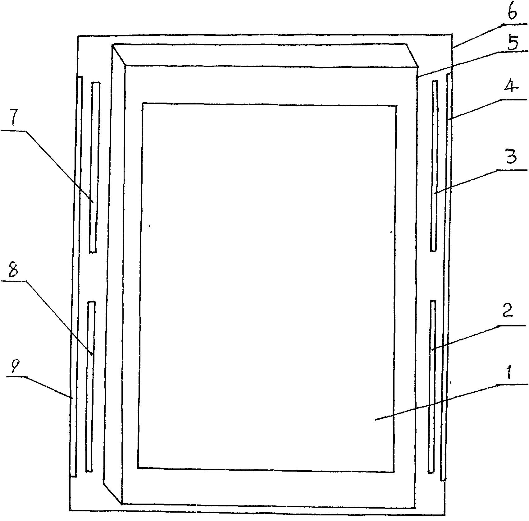
[0015] The present invention will be further described below in conjunction with the accompanying drawings and specific examples.

[0016] Such as figure 1 As shown, this example includes a frame 6 and a liquid crystal panel 5, and a visual target plate 1 (a high-grade acrylic plate in this example) engraved with a logarithmic vision chart is fixed on the front of the liquid crystal panel 5. Two cold cathode lamp tubes going up and down are respectively installed on the left and right sides of the liquid crystal panel 5, i.e. the first cold cathode lamp tube 7 on the upper left, the second cold cathode lamp tube 8 on the lower left, and the first cold cathode lamp tube on the upper right. Three cold cathode lamp tubes 3 and a fourth cold cathode lamp tube 2 at the bottom right. Reflectors are respectively installed on the outsides of the left and right cold cathode lamp tubes, that is, the first reflector 9 on the left and the second reflector 4 on the right. Under the effec...


PUM


Abstract

The invention relates to a liquid crystal logarithmic vision detector. A sighting target panel (1) marked with a logarithmic visual chart is fixed to the front face of a liquid crystal plate (5); both sides of the liquid crystal plate (5) are respectively provided with two cold cathode strip lamps moving up and down, namely a first cold cathode strip lamp (7) arranged at top left, a second cold cathode strip lamp (8) arranged at bottom left, a third cold cathode strip lamp (3) arranged at upper right, and a fourth cold cathode strip lamp (2) arranged at bottom right; and outer sides of the cold cathode strip lamps of both sides are respectively provided with reflex housings, namely a first reflex housing (9) arranged at the left side and a second reflex housing (4) arranged at the right side. The liquid crystal logarithmic vision detector selects a liquid crystal backlight plate and a novel design of light path transmission and combines the technology of high-frequency contravariance so as to achieve the aims of stable light source of the visual chart, flicker-free luminance, good bright screen uniformity, noise pollution prevention and longer service life of an illuminating system.

Description

technical field [0001] The invention relates to a logarithmic vision chart device, in particular to a liquid crystal logarithmic vision tester. Background technique [0002] The standard double-logarithmic eye charts used in various hospitals across the country now belong to the old technology 30 years ago, and fluorescent tubes are generally used as light sources. The biggest disadvantage is that after the power is turned on, the noise pollution is serious, there is a long time of flickering, the brightness is uneven, the life of the lighting system is short, and the bright screen is prone to discoloration, yellowing and darkening. There is a large difference between the test results and the actual vision of the subject. It is very thick and too long, and the volume is large. When the doctor checks the vision, the upper and lower spans are too large, which is inconvenient to use. Contents of the invention [0003] The technical problem to be solved by the present invent...

Claims


Application Information

Patent Timeline
IPC IPC(8): A61B3/032G02F1/13357
Inventor 孟繁华
Owner 孟繁华
Why Eureka
Try Eureka