Flow dividing element and fluid distributor

A technology of fluid distributor and shunt element, which is applied in fluid circulation arrangement, refrigeration components, refrigeration and liquefaction, etc., can solve the problems of high cost of liquid distributor, large installation environment restrictions, etc., achieve uniform and stable mixing, and low processing cost , the effect of even distribution

Pending Publication Date: 2021-06-22
QINGDAO HAIER AIR CONDITIONER GENERAL CORP LTD +2
View PDF0 Cites 0 Cited by
  • Summary
  • Abstract
  • Description
  • Claims
  • Application Information

AI Technical Summary

Problems solved by technology

[0006] Embodiments of the present disclosure provide a flow splitter and a fluid distributor to solve the problems of high cost and large restrictions on the installation environment of existing liquid distributors

Method used


Image

  • Flow dividing element and fluid distributor
  • Flow dividing element and fluid distributor
  • Flow dividing element and fluid distributor

Examples


Embodiment 1

[0167] A fluid distributor 200, in which the flow distribution element 100 is a cap-shaped flow separation element 120, the axial length H of the distribution cavity 210 is 30 mm, and the axial length C (ie, the first axial distance) of the front cavity 211 is 15 mm , the installation height h (that is, the second axial distance) of the flow splitting element 100 is 0mm. The height A of the cap-shaped shunt element 120 is 15 mm, and the characteristic length B of the port is 16.8 mm. The number of distribution branch pipes 230 is four. For other parameters, refer to the above related content.

[0168] In the fluid distributor 200 of Embodiment 1, the first characteristic ratio of the cap-shaped flow dividing element 120 is 0.9, the first ratio is 0.5, and the second ratio is 0. The molding method of the cap-shaped flow distribution element 120 can be any of the above three molding methods, for example, the wire mesh flow distribution element 100 obtained by braiding metal wi...

Embodiment 2

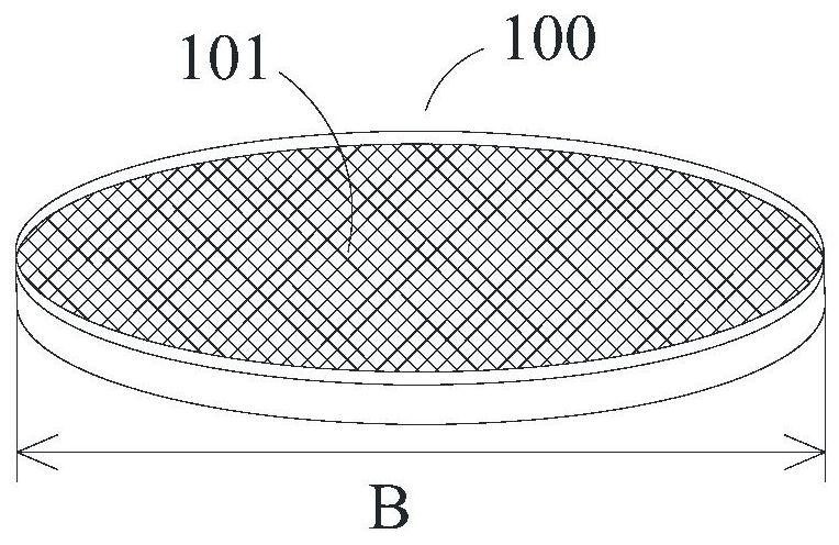
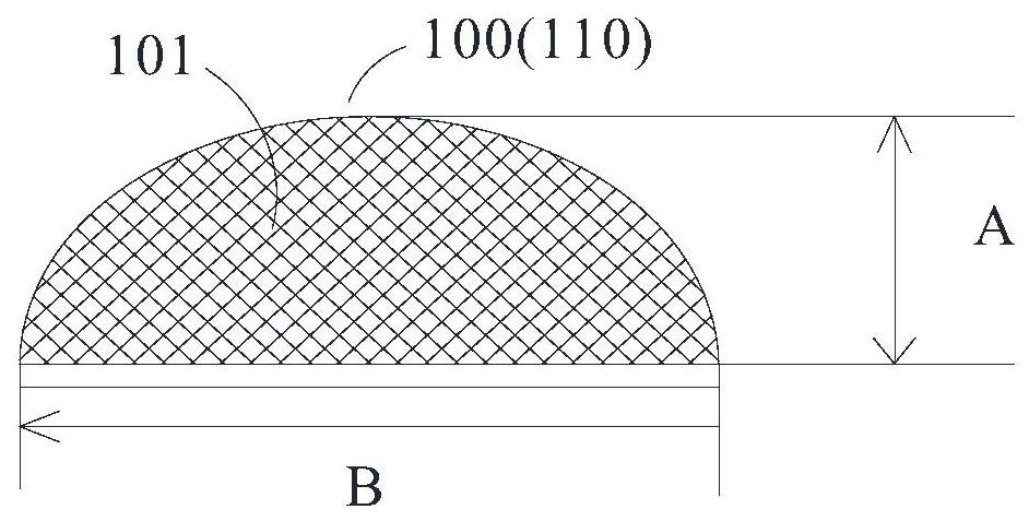
[0180] A fluid distributor 200, in which the flow distribution element 100 is a curved flow separation element 110, the axial length H of the distribution chamber 210 is 30mm, and the axial length C (that is, the first axial distance) of the front chamber 211 is 13mm , the installation height h (that is, the second axial distance) of the flow splitting element 100 is 10mm. The porosity of the curved flow splitting element 110 is 69%, the height A is 3 mm, and the characteristic length B of the port is 16.8 mm. The number of distribution branch pipes 230 is four. For other parameters, refer to the above related content.

[0181] In the fluid distributor 200 of this embodiment, the first characteristic ratio of the curved flow dividing element 110 is 0.18, the first ratio is 0.43, the second ratio is 0.3, and the third ratio is 0.66. The above-mentioned three molding methods can be used for forming the curved flow distribution element 110 , for example, the wire mesh flow dist...


PUM


Abstract

The invention relates to the technical field of fluid distribution, and discloses a flow dividing element which comprises an element body. A plurality of flow dividing through holes are distributed on the element body; the porosity of the element body is 60 percent to 78 percent; and the included angle between the axis of each flow dividing through hole and the normal of the plane where the flow dividing through hole is located is 0 degree to 15 degrees. By controlling the porosity of the flow dividing through holes and setting the forming directions of the flow dividing through holes, a better flow mixing effect can be achieved on fluid, and the fluid flowing through the flow dividing through holes can be evenly and stably mixed; the fluid distributor comprising the flow dividing element is uniform in liquid distribution, so that good uniformity and stability are achieved, and the uniformity and the stability of the fluid distributor can be even superior to the uniformity and the stability of an existing venturi distributor; and furthermore, a heat exchanger adopting the fluid distributor is uniform in flow distribution, and the energy efficiency is improved. Meanwhile, the flow dividing element provided by the embodiment of the invention is simple in structure, easy to machine and form and low in machining cost. The invention further discloses the fluid distributor.

Description

technical field [0001] The present application relates to the technical field of fluid dispensing, for example, to a flow dividing element and a fluid distributor. Background technique [0002] At present, in the refrigeration system, except for the case where the amount of cooling (heat) is very small, the heat exchanger generally adopts the form of multi-channel parallel connection to keep the refrigerant at an optimal flow rate, and at the same time, the pressure drop on the refrigerant side of the heat exchanger is limited within a certain range. , and when the refrigerant with uniform gas-liquid mixture is equally distributed to each branch, the efficient use of the heat exchanger can be ensured. When the refrigerant cannot be evenly distributed to each branch, it will cause different degrees of superheat at the outlets of each branch of each heat exchanger, and the branch with less liquid supply will enter the overheating zone prematurely, and the coefficient of the he...

Claims


Application Information

Patent Timeline
Patent Type & Authority Applications(China)
IPC IPC(8): F25B41/42F25B43/00
CPCF25B43/00
Inventor 丁爽王飞张心怡崔文娟袁俊军李阳许文明
Owner QINGDAO HAIER AIR CONDITIONER GENERAL CORP LTD
Why Eureka
Try Eureka