
Apparatus and method for applying coating liquid to cylindrical substrate, and electrophotographic photoreceptor produced by that method and electrophotographic apparatus provided with the same

Active Publication Date: 2007-03-08
SHARP KK
View PDF6 Cites 1 Cited by
  • Summary
  • Abstract
  • Description
  • Claims
  • Application Information

AI Technical Summary

Benefits of technology

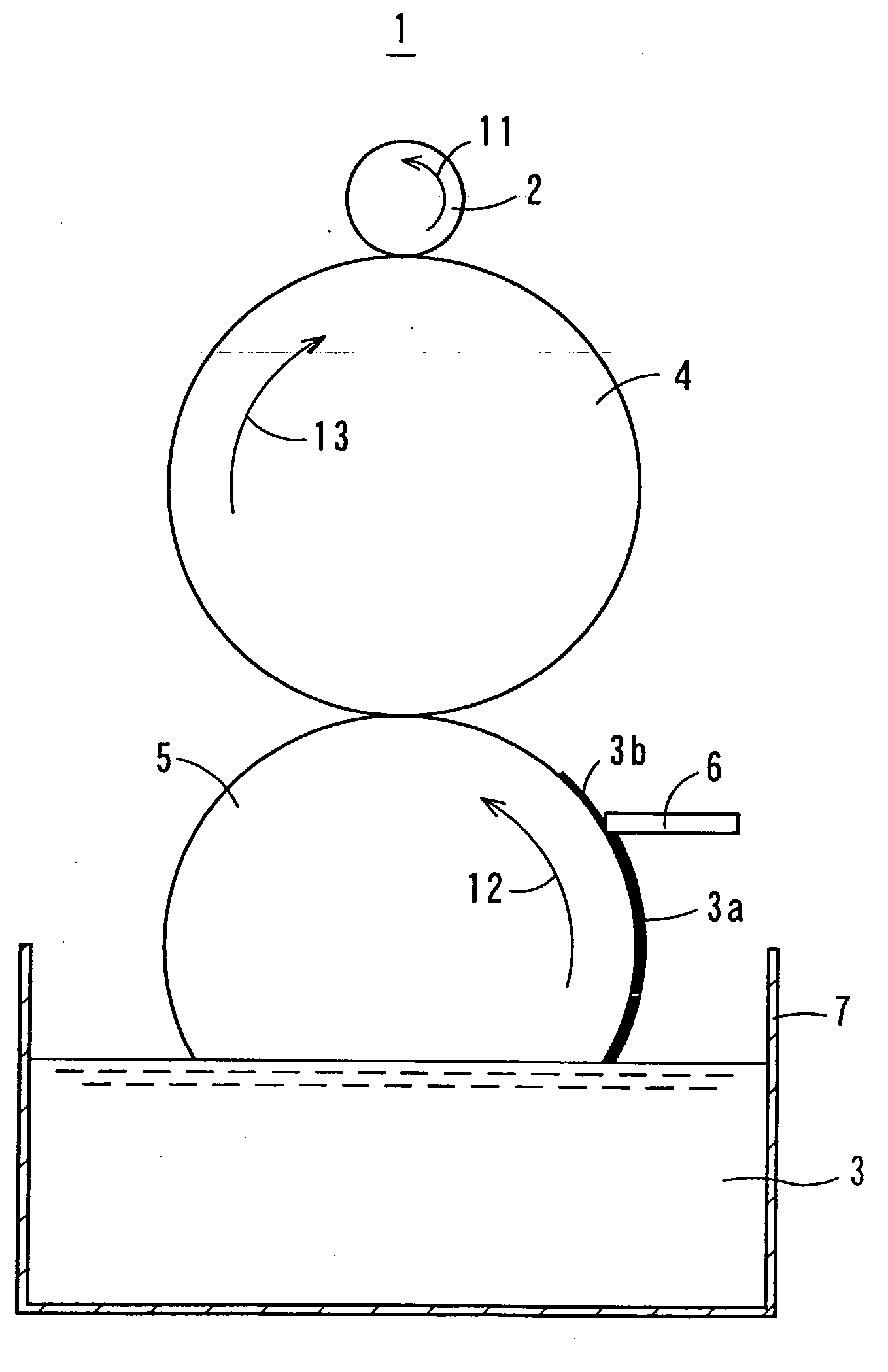
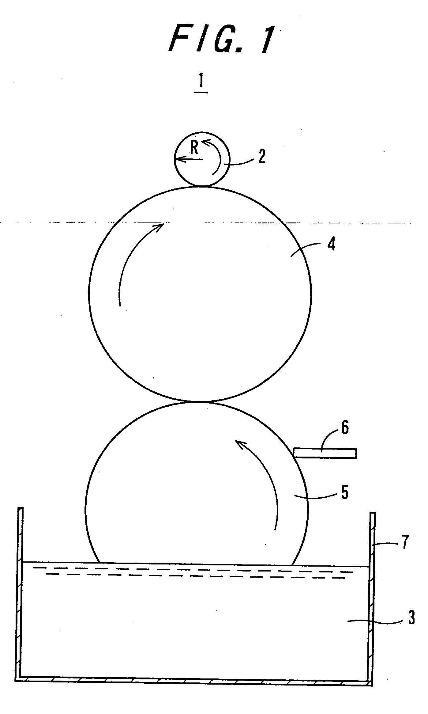
[0014] An object of the invention is to provide an apparatus and a method for applying a coating liquid to a cylindrical substrate, from which a coating film that is free from unevenness of the thickness, is seamless and has excellent uniformity can be obtained with high production efficiency.

Problems solved by technology

However, these related art coating methods involve such problems that a uniform coating film is not obtained and that the production efficiency is poor.
For example, the spray coating method involves such a problem that when a solvent having a low boiling point is used in the coating material for electrophotographic photoreceptor, the solvent contained in the coating material is vaporized on the way of arrival of the coating material at the peripheral surface of the substrate, whereby the concentration of solids in the coating material increases, and therefore, when the coating material arrives at the substrate, it does not sufficiently spread on the peripheral surface of the substrate, and the surface of the coating film becomes irregular so that a smooth coating film surface is not obtained, whereby a coating film having a uniform thickness is not obtained.
When coating is continued in such a state that the fixing of the coating film is insufficient, in the case where a desired thickness is thick, there is encountered a problem that sagging of the coating material occurs so that a coating film having a uniform thickness is not obtained, either.
In order to avoid this problem, the coating material may be dividedly coated several times. However, this method involves such problems that since coating and drying must be repeatedly carried out until the coating film becomes dry to the touch (the state that the coating film becomes dry to a degree that a trace does not remain even by finger touch), a time required for achieving works is long and that steps thereof are extremely complicated.
The coating film formed in the interior and end face of the substrate becomes an obstacle in installing a flange, etc. in the substrate.
Accordingly, in order to formulate a substrate in which a coating film is formed in the interior and end face thereof into a substrate for electrophotographic photoreceptor, there is encountered a problem that the coating film formed in the interior and end face of the substrate must be peeled away.
Further, since the thickness of the coating film is largely affected by physical properties of the coating material and a lifting rate after dipping, when lifting is carried out at a constant rate, a thickness difference between the upper end and the lower end of the substrate is generated.
However, that control is difficult.
Also, there is encountered a problem that in order to form a coating film having a uniform thickness, the lifting rate after dipping must be made slow.
Thus, high production efficiency was not obtained.
According to the blade coating method, though high producibility is obtained, there is encountered a problem that when the blade is moved backward, a phenomenon wherein a part of the coating film coated on the substrate swells occurs due to a surface tension of the substrate so that the thickness becomes non-uniform by this swelling.
The roll coating method involves a problem caused by special characteristics of a substrate as a material to be coated that it is cylindrical, namely, residence of a coating material generated when a cylindrical substrate as a material to be coated rotates and the once coated surface returns repeatedly to a coating portion makes the thickness non-uniform.
However, according( to the related art technology disclosed in JP-A 3-12261, in the case where the substrate makes only one revolution, there is encountered a problem that not only it is difficult to obtain a uniform coating film, but also a seam of the coating material generated when the substrate is kept away from the roll remains.
However, this method involves such a problem that the thickness must be precisely controlled in expectation of an amount of the residence of the coating material to be subjected to leveling in advance and the substrate must be kept while rotating for a period of time necessary for achieving leveling, resulting in a lowering of the production efficiency.
Also, though a gravure offset method that has hitherto been employed is excellent as a method of forming a certain specific pattern with good precision, it is concerned with a technology fundamentally different from so-called “coating” of forming a uniform coating film and involves such a problem that when it is intended to form a coating film on a cylindrical substrate, a pattern of a plate remains, or a seam is formed.

Method used


Image

  • Apparatus and method for applying coating liquid to cylindrical substrate, and electrophotographic photoreceptor produced by that method and electrophotographic apparatus provided with the same
  • Apparatus and method for applying coating liquid to cylindrical substrate, and electrophotographic photoreceptor produced by that method and electrophotographic apparatus provided with the same
  • Apparatus and method for applying coating liquid to cylindrical substrate, and electrophotographic photoreceptor produced by that method and electrophotographic apparatus provided with the same

Examples


examples

[0115] Examples of the invention will be hereunder described. Incidentally, in the Examples, though the preparation of electrophotographic photoreceptors is enumerated, the invention is never limited to the electrophotographic photoreceptors but can be used for applying a coating liquid to a cylindrical substrate in other fields.

[0116] (Preparation of Coating Liquid)

[0117] Coating liquids A1 to E1 for charge-generating layer and coating liquids A2 to E2 for charge-transporting layer were prepared in the following manners.

[0118] [Coating Liquid A1 for Charge-Generating Layer]

[0119] Materials shown in Table 2 were dispersed in a homogenizer for 10 minutes to prepare a coating liquid A1 for charge-generating layer.

TABLE 2Non-metal phthalocyanine (Fastogen1.6parts by weightBlue 8120BS, manufactured byDainippon Ink and ChemicalsIncorporated):AEROSIL R972 (manufactured by Nippon0.5parts by weightAerosil Co., Ltd.):Polycarbonate resin Z8008.5parts by weight(manufactured by Mitsubishi ...


PUM

PropertyMeasurementUnit
Angular velocityaaaaaaaaaa
Lengthaaaaaaaaaa
Shapeaaaaaaaaaa

Abstract

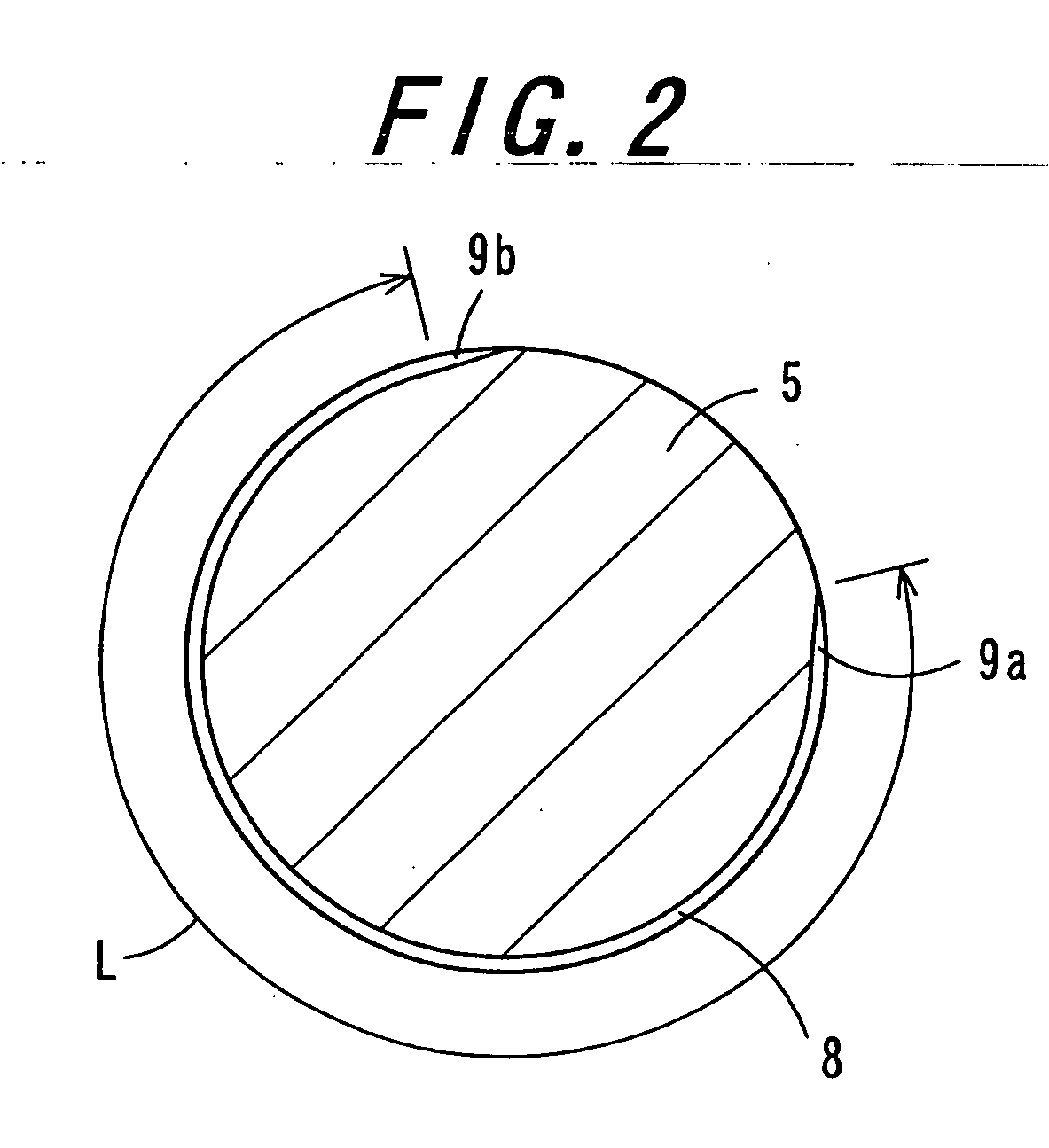
A coating liquid to be used for coating has a loss tangent tan δ of from 1 to 10 at a frequency of 6.28 radians / sec. A coating liquid supplying roll has a fine concave portion in at least a part of the circumferential length thereof, and in the vicinities of the both circumferential ends of the fine concave portion, the fine concave portion 8 has concave depth decreasing portions formed in such a manner that the depth of a fine concave decreases. The fine concave portion is constructed in such a manner that the sum L (=L1+L2) of a circumferential length L1 of a portion in which the fine concaves are formed in substantially the same depth and a circumferential length L2 of one concave depth decreasing portion becomes an integral multiple (1 or more) of a circumference Lc of the cylindrical substrate.

Description

BACKGROUND OF THE INVENTION [0001] 1. Field of the Invention [0002] The present invention relates to an apparatus and a method for applying a coating liquid to a cylindrical substrate and to an electrophotographic photoreceptor produced by that method and an electrophotographic apparatus provided with the same. [0003] 2. Description of the Related Art [0004] Technologies for applying a coating liquid to a cylindrical substrate have hitherto been employed in various fields. Here, the preparation of an electrophotographic photoreceptor will be hereunder enumerated. Incidentally, even in limiting to the electrographic field, application of a coating liquid to a cylindrical substrate is employed in the preparation of not only electrophotographic photoreceptors but also charging rolls, transfer rolls, fixing rolls, and so on. [0005] The electrophotographic photoreceptor includes ones in which a lamination type photosensitive layer is formed by successively applying a coating material for...

Claims


Application Information

Patent Timeline
IPC IPC(8): G03G5/00B05D3/02G03G21/00B05C1/00B05C1/02B05C1/08B05D1/28G03G5/04G03G5/05G03G5/06G03G15/00G03G15/10
CPCB05C1/02B05C1/0808B05C1/0813B05D1/28G03G15/104G03G5/0525G03G5/0564G03G5/0614G03G5/0517G03G5/061443G03G5/061473Y10S118/14Y10S118/15
Inventor ISHIDA, KAZUYAOBATA, TAKATSUGUWASHO, JUNICHI
Owner SHARP KK
Learn More