
Noise reduction device and method thereof

a technology of noise reduction device and noise reduction method, which is applied in the field of noise reduction device and method, can solve the problems of permanent hearing loss, young people seem to be experiencing hearing loss at an astonishing rate, and the inner ear eardrum is impacted, so as to achieve the effect of reducing the low-frequency noise range and the high-frequency range noise reduction

Inactive Publication Date: 2008-07-03
IND TECH RES INST
View PDF20 Cites 36 Cited by
  • Summary
  • Abstract
  • Description
  • Claims
  • Application Information

AI Technical Summary

Benefits of technology

[0009]The present invention provides a noise reduction device with at lease one of noise reduction circuit and filtering cavity structure design, by which the reduction of audio high-frequency range noises can be achieved by at least an operation of a low-pass filter formed by the cavity structure, and the reduction of audio low-frequency noise range can be achieved by the operation of the noise reduction circuit, so that audio full frequency range noise reduction can be achieved as well.
[0010]The present invention also provides a noise reduction device that improves the ear discomfort of imbalance in air pressure, caused by the sealing of the ear canal completely for noise reduction.
[0016]a speaker for receiving the electrical signal generated by the noise reduction circuit, using the received electrical signal to generate an out of phase acoustic signal accordingly, and feeding the out of phase acoustic signal into the cavity to interfere with the noise signal inside the cavity, thereby reducing the noise signal inside the cavity.
[0022]With the aforesaid device and method, not only audio high-frequency range noises can be reduced by an operation of a low-pass filter formed by the combined structure of the cavity and the ducts, but also audio low-frequency noise range is reduced by the noise reduction circuit as it can direct the speaker to generate an out of phase acoustic signal for canceling out the audio low-frequency range noise, so that audio full frequency range noise reduction can be achieved.

Problems solved by technology

Long exposure to noise can damage the eardrum of the inner ear, causing permanent hearing loss.
Even only exposing to a loud noise for a short period of time might cause discomfort.
Recent reports show that today's young people seem to be experiencing hearing loss at an astonishing rate, and that personal audio equipment seems to be contributing to that trend as like any other sound, music can cause hearing loss if it is loud enough and exposure is long enough.
Especially when earbuds or earpieces are often used with such personal audio equipment for audio entertainment, and users of such personal audio equipment are consciously exposing themselves to loud volumes while situating in a noisy environment, which poses a threat to noise-induced hearing loss.
However, it is not easy to carry because of its large size.
However, although the in-the-ear earpiece can provide better acoustic isolation effect, it may cause ear discomfort since it can seal the ear canal completely and therefore cause imbalance in air pressure.
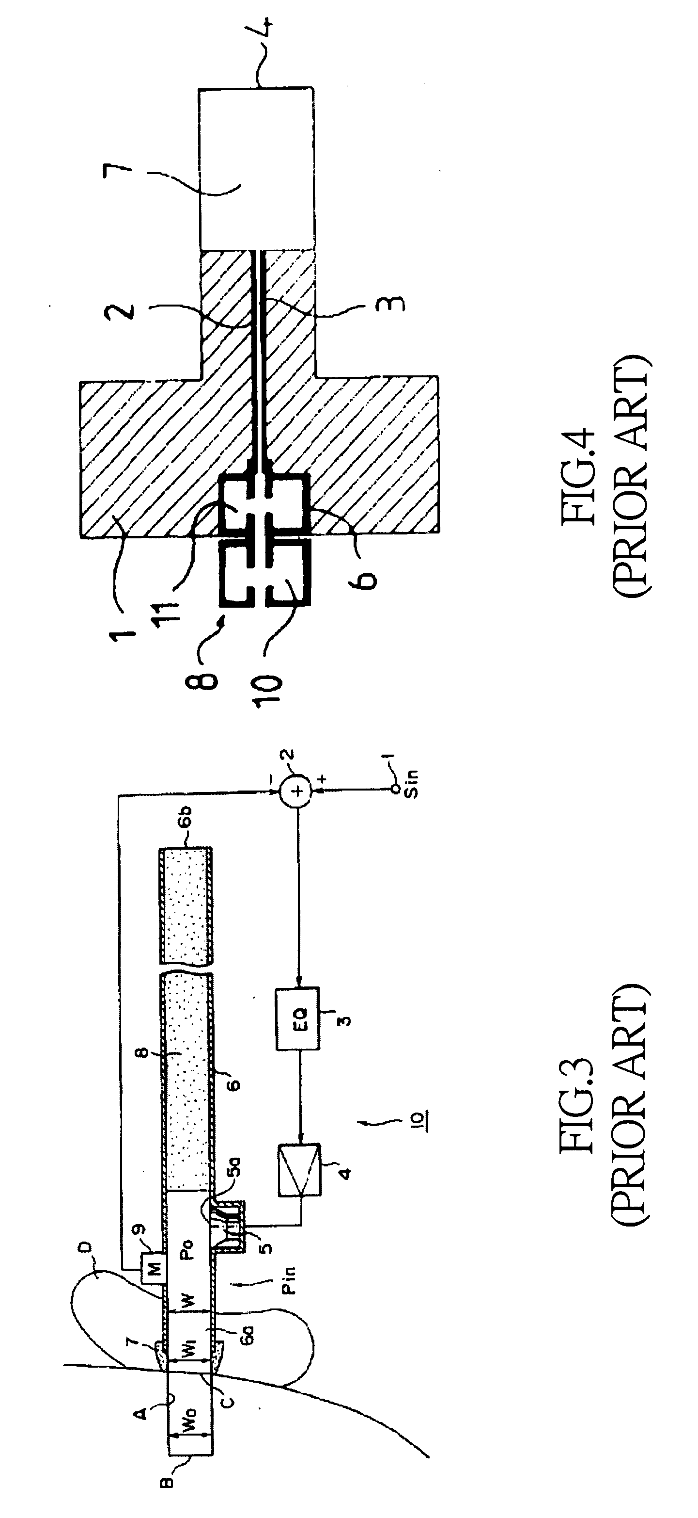
Nevertheless, it can only be used for canceling out noises of low-frequency range, such as those of several kHz, but cannot be used for canceling out noises of high-frequency range since it cannot synchronize with the phases of those high-frequency noises.
However, the primary design of using an active circuit for noise attenuation remains the same and thus they all fail in high-frequency noise cancellation.
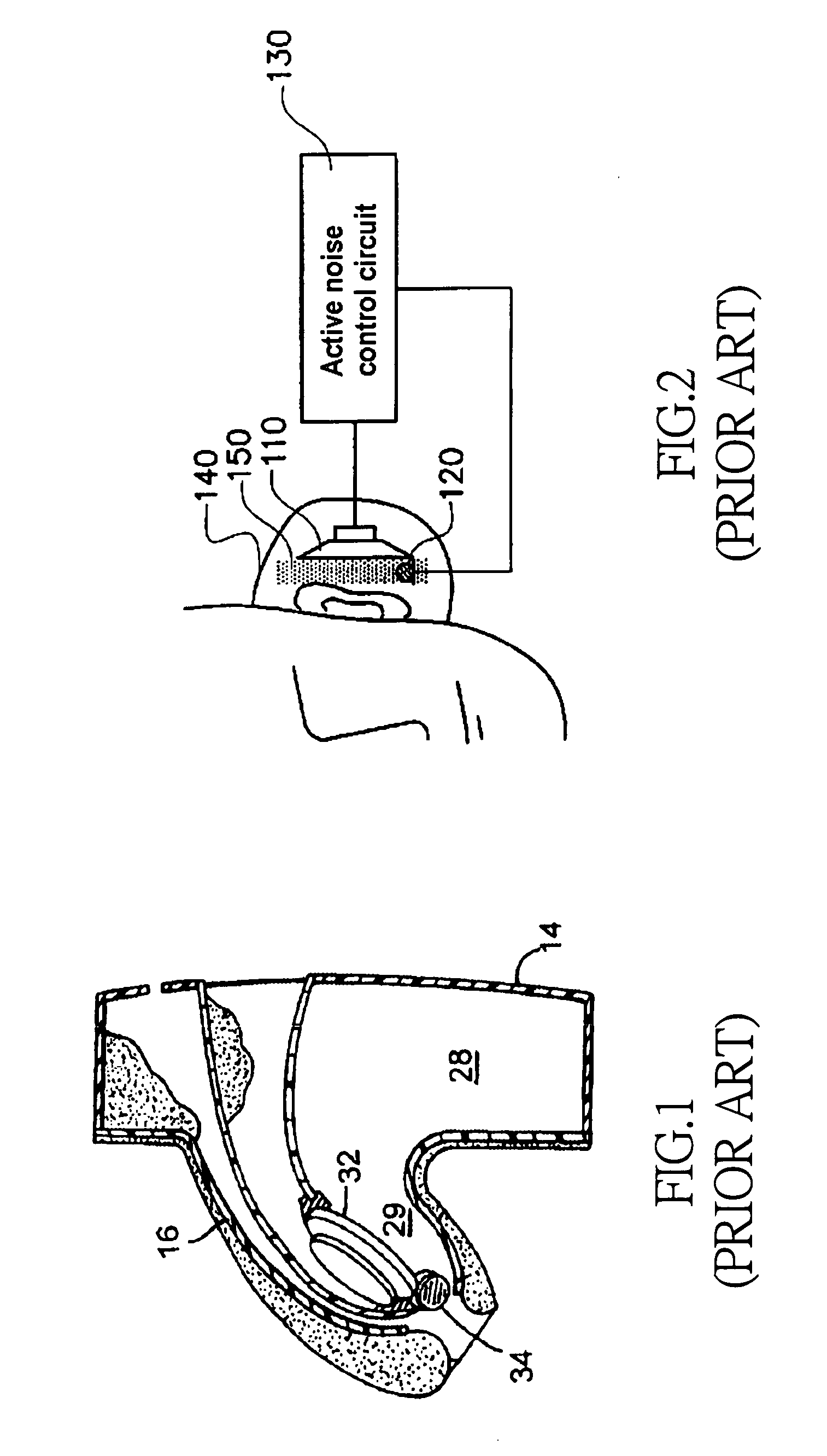
However, as the cavity 28 and the passageway 29 are not structured to equip with filtering ability, noise of high-frequency range cannot be filtered thereby.
Nevertheless, the aforesaid earphone can only attenuate low frequency noise.

Method used


Image

  • Noise reduction device and method thereof
  • Noise reduction device and method thereof
  • Noise reduction device and method thereof

Examples


Embodiment Construction

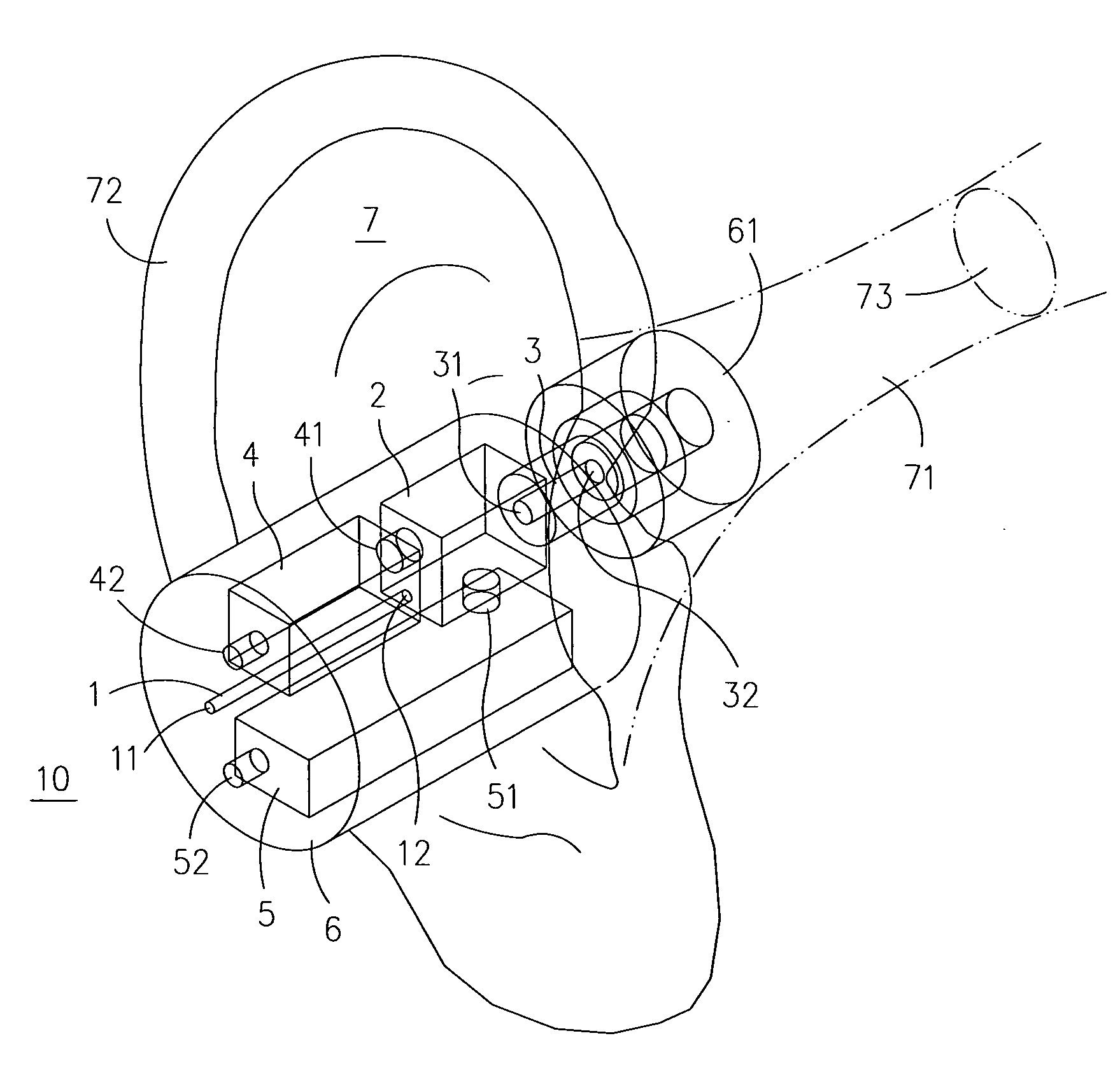
[0035]The noise reduction device in an exemplary embodiment of the present invention can be divided into two parts, one of which is an acoustic wave filter and the other is a noise reduction circuit. The structure of the acoustic wave filter is shown in FIG. 5 and FIG. 6. The noise reduction device 10 includes a housing 6 with a cavity 2 defined therein, in which the cross-sectional area of the cavity 2 is represented as S2 and its length is represented as L2. An outer duct 1 is arranged at an end of the cavity 2 while arranging an inner duct 3 at another end of the cavity 2. The outer duct 1 has an input end 11 and an output end 12. The input end 11 extends through the housing 6 and is channeled with ambient environment of the housing 6, and the output end 12 is connected and channeled with the cavity 2. The cross-sectional area of the outer duct 1 is represented as S1 and its length is represented as L1. The inner duct 3 has an input end 31 and an output end 32. The input end 31 i...


PUM


Abstract

A noise reduction device include at east a cavity; a plurality of ducts noise reduction, at least one of the ducts being connected to the cavity for transmitting an acoustic signal including a noise signal into / out of the cavity; a noise reduction circuit, for receiving the acoustic signal including the noise signal and generating an electrical signal; a microphone for receiving the acoustic signal inside the cavity, converting the received acoustic signal into another electrical signal and transmitting the electrical signal to the noise reduction circuit; and a speaker for receiving the electrical signal generated by the noise reduction circuit, using the received electrical signal to generate an out of phase acoustic signal accordingly, and feeding the out of phase acoustic signal into the cavity to interfere with the noise signal inside the cavity. With the noise reduction circuit and cavity structure designed in the noise reduction device, the full range of noise is attenuated

Description

FIELD OF THE INVENTION[0001]The present invention relates to a noise reduction device and method. With noise reduction circuit and cavity structure designed in the noise reduction device, it can achieve reduction of audio high-frequency range noises by an operation of a low-pass filter formed by the cavity structure, and the reduction of audio low-frequency range noise by the noise reduction circuit as it also can direct a speaker to generate an out of phase acoustic wave for canceling out the audio low-frequency range noise, so that audio full frequency range noise reduction is achieved.BACKGROUND OF THE INVENTION[0002]Long exposure to noise can damage the eardrum of the inner ear, causing permanent hearing loss. Even only exposing to a loud noise for a short period of time might cause discomfort. Recent reports show that today's young people seem to be experiencing hearing loss at an astonishing rate, and that personal audio equipment seems to be contributing to that trend as like...

Claims


Application Information

Patent Timeline
Patent Type & Authority Applications(United States)
IPC IPC(8): A61F11/06
CPCH04R1/1083G10K11/1788G10K11/17861G10K11/17833G10K11/17857G10K11/17875
Inventor SUNG, PO-HSUNCHU, CHUN-HSUN
Owner IND TECH RES INST
Learn More