Multi-channel optical coupling device, electronic equipment, lead frame member, and fabrication method for multi-channel optical coupling device

a fabrication method and optical coupling technology, applied in the field of multi-channel optical coupling devices, can solve the problems of insufficient measures aimed at minimizing light interference between adjacent optical coupling elements (channels) among the plurality of optical coupling elements, inability to sufficiently block light between the optical coupling elements p, p, etc., to achieve effective optical interference, reduce the number of external terminals, and effectively prevent optical interference

Inactive Publication Date: 2008-07-03
SHARP KK
View PDF3 Cites 21 Cited by
  • Summary
  • Abstract
  • Description
  • Claims
  • Application Information

AI Technical Summary

Benefits of technology

The present invention provides a way to create a multi-channel optical coupling device with reduced optical interference between neighboring components. This means that more data can be transmitted through one network without causing problems like delays or errors. Additionally, this reduces the amount of wiring needed which saves money on manufacturing costs. A new method for making the leads used in these devices has also been developed. Overall, this technology helps improve performance and efficiency in electronic equipment.

Problems solved by technology

The technical problem addressed in this patent is how to improve the performance and reliability of multi-channel optical coupling devices made up of multiple optical coupling elements. One issue is that the current methods involve inducing stress due to changes in environmental factors like temperature or pressure during the packaging process, resulting in cracking or damage to components. Another challenge is ensuring effective protection against light interference without adding too many external terminals and making subsequent assembly more complex.

Method used


Image

  • Multi-channel optical coupling device, electronic equipment, lead frame member, and fabrication method for multi-channel optical coupling device
  • Multi-channel optical coupling device, electronic equipment, lead frame member, and fabrication method for multi-channel optical coupling device
  • Multi-channel optical coupling device, electronic equipment, lead frame member, and fabrication method for multi-channel optical coupling device

Examples


Embodiment Construction

[0092]The embodiments of the present invention are explained in detail by referring to the attached drawings.

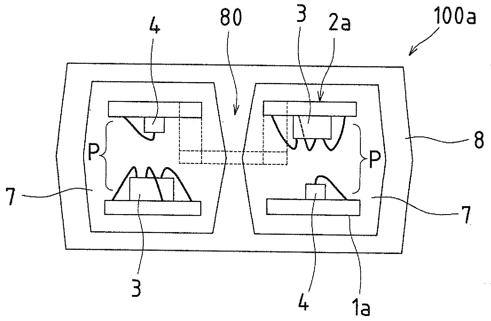
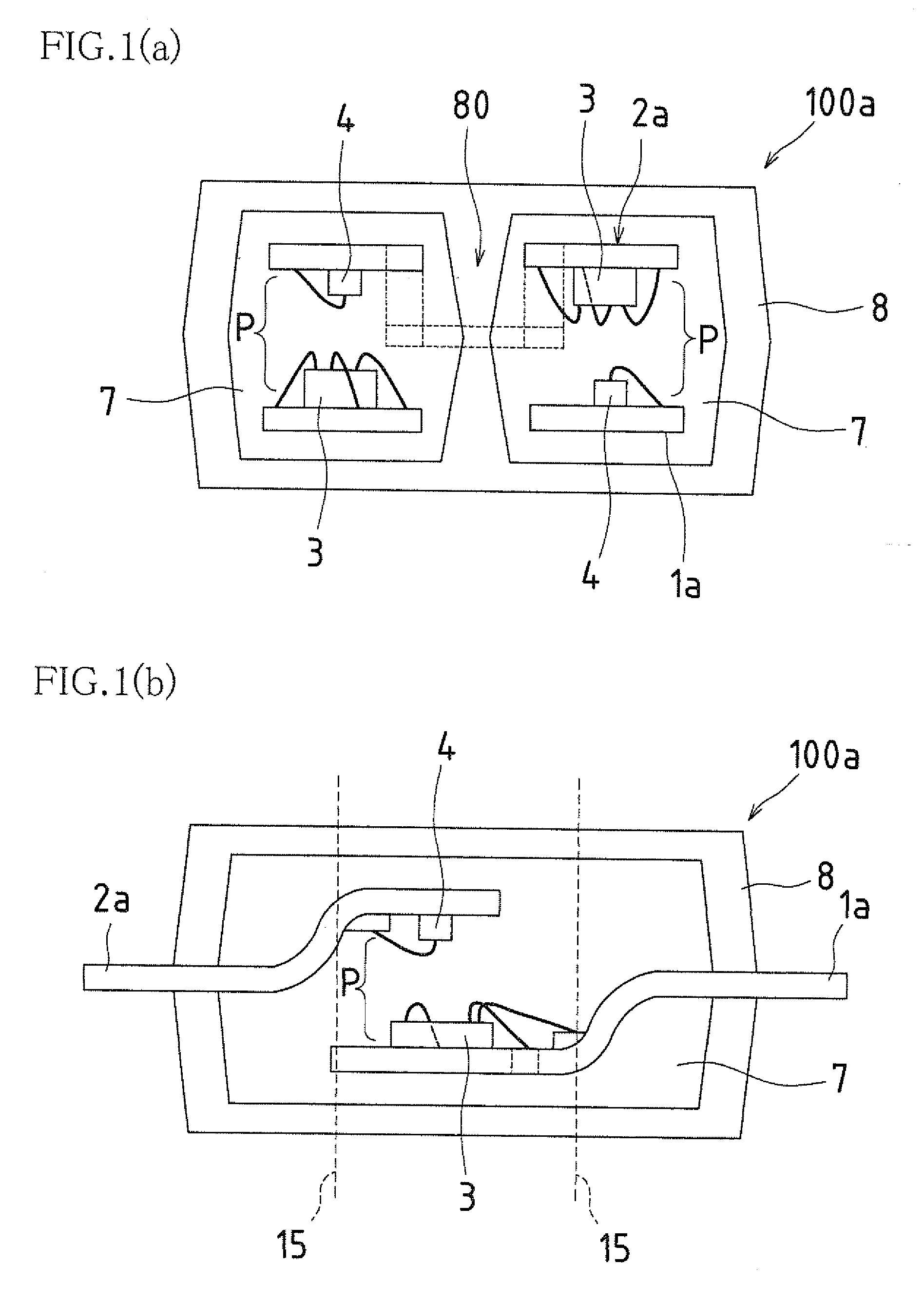
[0093]FIG. 1(a) and FIG. 1(b) are diagrams illustrating an embodiment of the multi-channel optical coupling device of the present invention, with FIG. 1(a) being a schematic cross-section of the optical coupling device as viewed from the side and FIG. 1(b) being a schematic cross-section of the optical coupling device as viewed from the front.

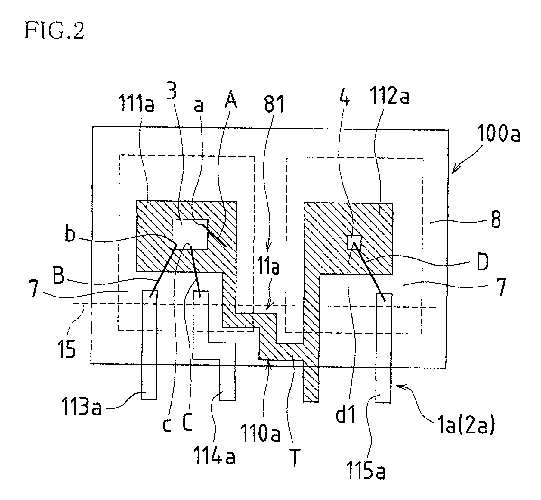
[0094]FIG. 2 is a schematic plan view highlighting one of the lead frames 1a used in the multi-channel optical coupling device 100a illustrated in FIG. 1(a) and FIG. 1(b).

[0095]It should be noted that, in FIG. 2, the configuration of the other lead frame 2a illustrated in FIG. 1(a) and FIG. 1(b) is substantially identical to the configuration of the first lead frame 1a and is represented thereby in FIG. 2. Accordingly, in FIG. 2, the other lead frame 2a is shown in parentheses after reference numeral 1a. The same is also true with respec...


PUM


Abstract

In one embodiment, in a multi-channel optical coupling device, which is obtained by individually encapsulating a plurality of optical coupling elements within primary packages of light transmitting resin while encapsulating them within a secondary package of light blocking resin, a lead frame is provided with a common lead used to electrically interconnect the optical coupling elements, with the common lead being partially decoupled at the boundary location between the optical coupling elements.

Description


Claims


Application Information

Patent Timeline
Owner SHARP KK
Why Eureka
Try Eureka