
Configurable post-amplifiers that are capable of being configured to perform either substantially linear or limiting amplification for use in optical receivers

a post-amplifier and configuration technology, applied in the field of signal amplification, can solve the problems of edc not being able to compensate for optical dispersion, impede the accurate recovery of optical signals,

Inactive Publication Date: 2008-07-03
INTEL CORP
View PDF10 Cites 16 Cited by
  • Summary
  • Abstract
  • Description
  • Claims
  • Application Information

AI Technical Summary

Problems solved by technology

A significant amount of optical dispersion may tend to hinder accurate recovery of the data represented by the optical signals.
In addition to amplifying the voltage, the limiting post-amplifiers may tend to remove the upper and / or lower extents of the incoming signal or otherwise alter the shape of the received optical signals.
Such alteration of the shape of the received optical signals may tend to hinder the ability of EDC to compensate for optical dispersion.

Method used


Image

  • Configurable post-amplifiers that are capable of being configured to perform either substantially linear or limiting amplification for use in optical receivers
  • Configurable post-amplifiers that are capable of being configured to perform either substantially linear or limiting amplification for use in optical receivers
  • Configurable post-amplifiers that are capable of being configured to perform either substantially linear or limiting amplification for use in optical receivers

Examples


Embodiment Construction

[0015]In the following description, numerous specific details are set forth. However, it is understood that embodiments of the invention may be practiced without these specific details. In other instances, well-known circuits, structures and techniques have not been shown in detail in order not to obscure the understanding of this description.

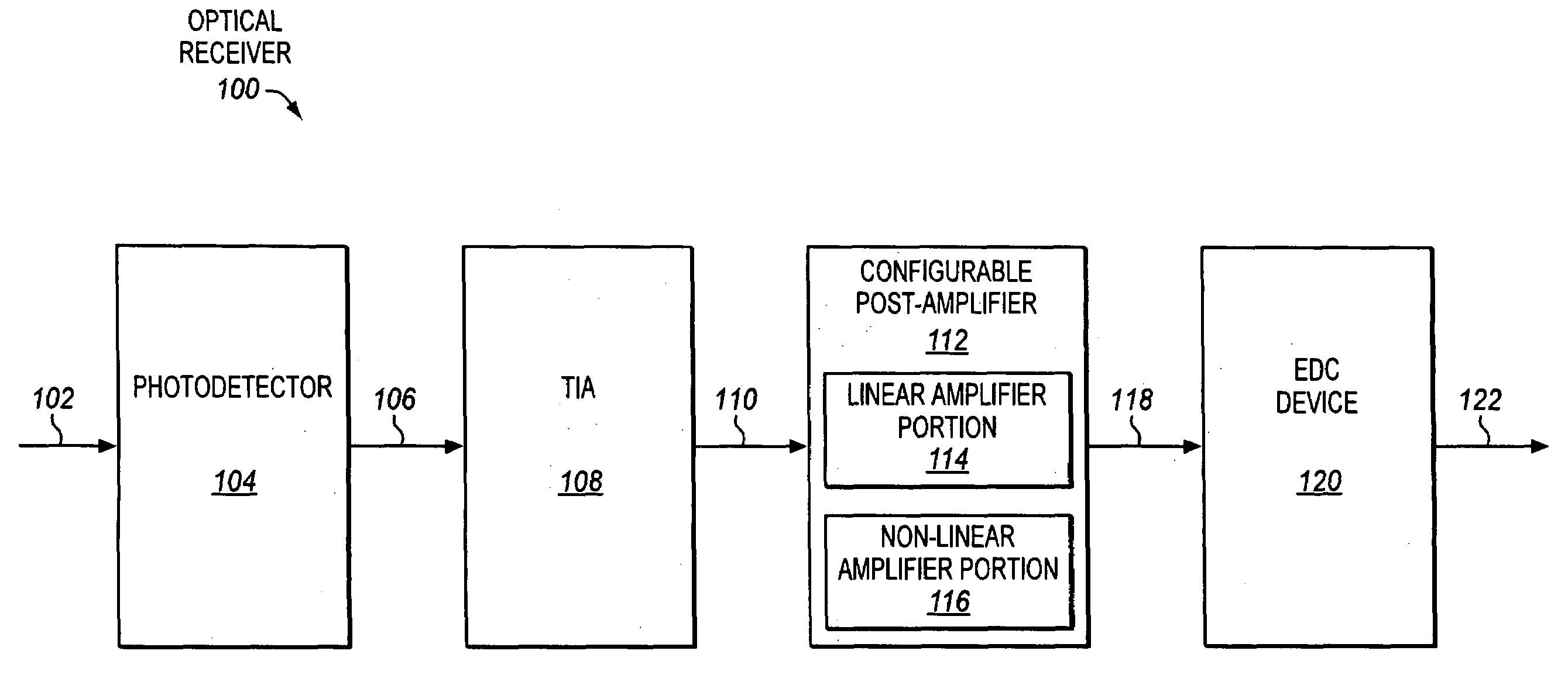
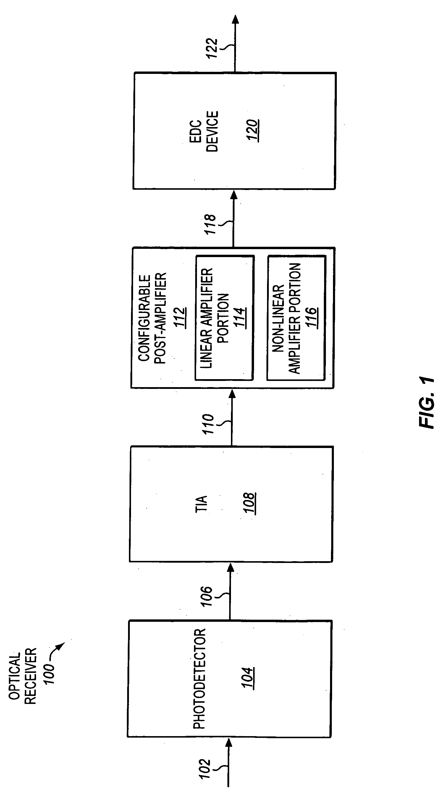
[0016]FIG. 1 is a block diagram of an optical receiver 100, according to one or more embodiments of the invention. The optical receiver includes a configurable post-amplifier, according to one or more embodiments of the invention, which will be discussed further below.

[0017]The optical receiver includes a photodetector 104. Examples of suitable photodetectors include, but are not limited to, avalanche photodiodes (APDs), positive-intrinsic-negative (PIN) photodiodes, and other photodetectors known in the arts. The photodetector and / or the optical receiver may be optically coupled with one or more optical fibers, other optical waveguides, or oth...


PUM


Abstract

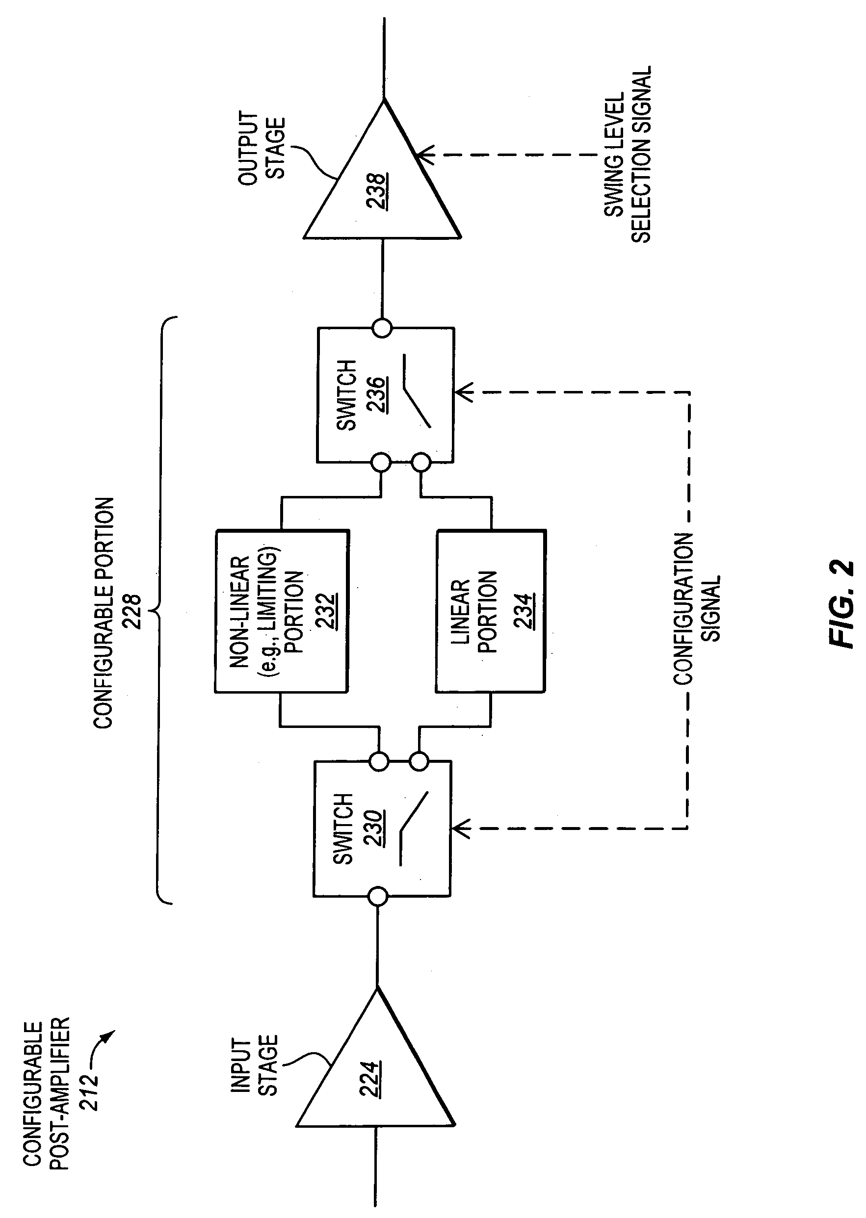
Configurable amplifiers for optical receivers and transceivers are disclosed. In one aspect, a configurable amplifier may be coupled with an output of a current-to-voltage converter to receive a voltage. The configurable amplifier may be capable of being configured to use either a substantially linear amplifier portion or a substantially non-linear amplifier portion to amplify the voltage.

Description

BACKGROUND[0001]1. Field[0002]Embodiments of the invention relate to the field of optical receivers. In particular, embodiments of the invention relate to signal amplification for optical receiver applications.[0003]2. Background Information[0004]Optical transceivers may be used to exchange data rapidly over optical fibers. However, optical dispersion may be introduced into the optical signals transmitted over the optical fibers. The amount of optical dispersion tends to increase with increasing transmission distance. The amount of optical dispersion may also vary with fiber type. A significant amount of optical dispersion may tend to hinder accurate recovery of the data represented by the optical signals.[0005]Electronic dispersion compensation (EDC) is one known technique that may be used to reduce optical dispersion. However, optical receivers commonly include a so-called limiting post-amplifier to amplify the voltage output by a transimpedance amplifier (TIA). In addition to amp...

Claims


Application Information

Patent Timeline
IPC IPC(8): H03F3/08H04B10/06
CPCH03F1/0277H04B10/693H03F3/211H03F3/08
Inventor CHENG, HENGJUKRAUSE, CHRISTINE
Owner INTEL CORP
Learn More