

Air conditioner fan
- Summary
- Abstract
- Description
- Claims
- Application Information
AI Technical Summary
Benefits of technology
Problems solved by technology
Method used
Image

Examples
first embodiment
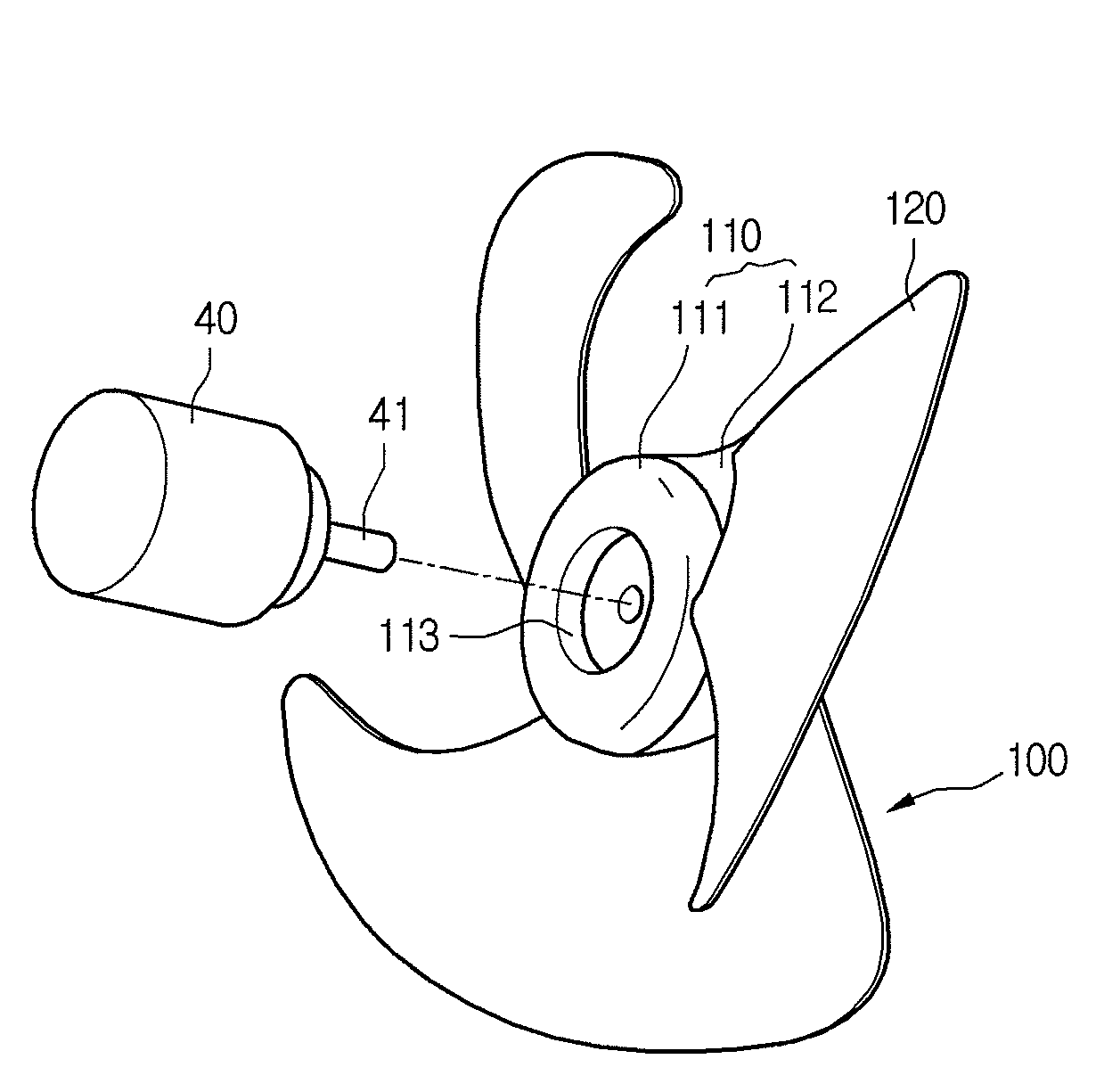
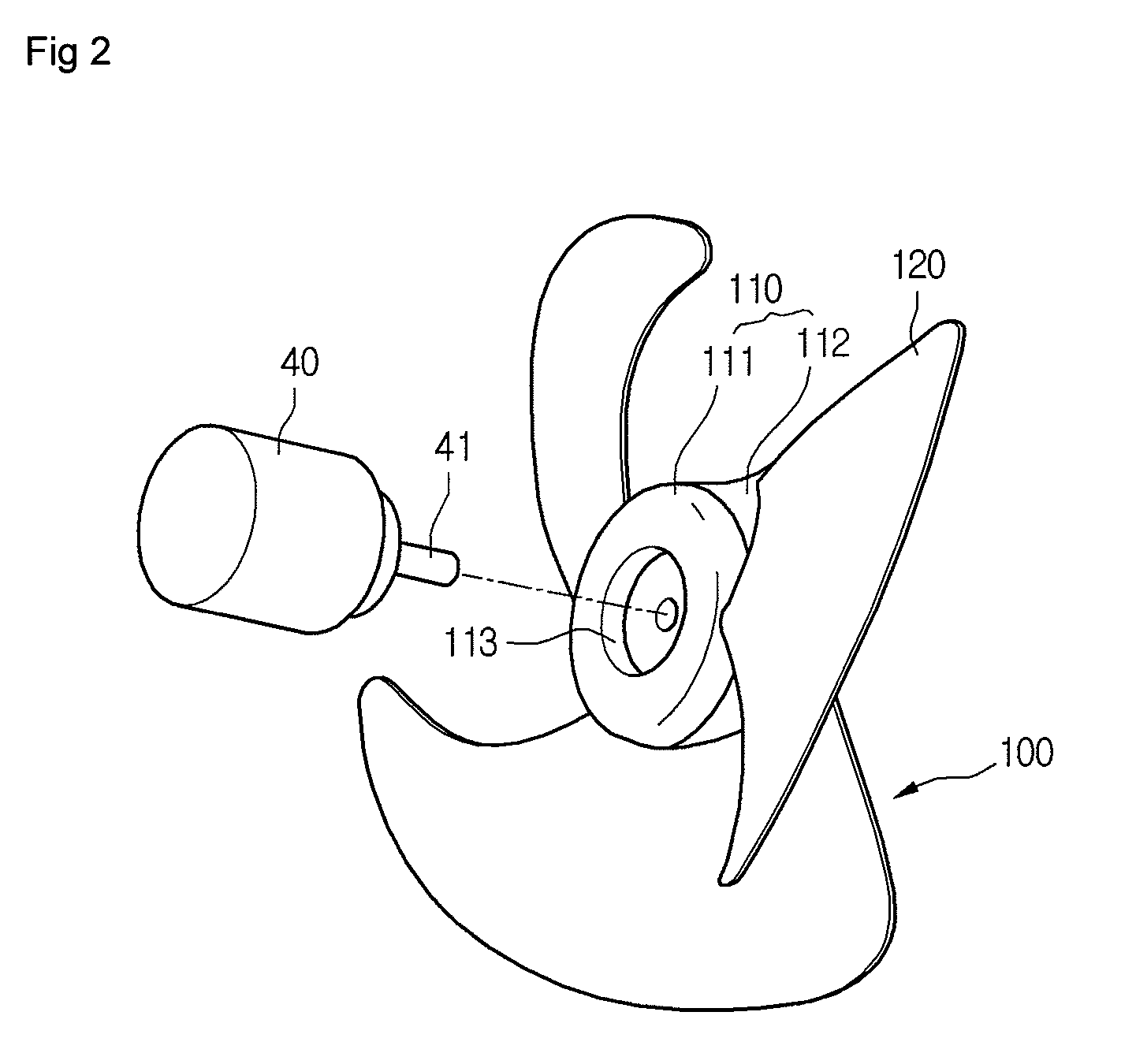
[0042]FIG. 2 is an exploded perspective view illustrating the motor 40 and the fan 100, and FIG. 3 is a side view illustrating a hub 110 of the fan 100 according to a
[0043]Referring to FIGS. 2 and 3, the fan 100 includes the hub 110 and a plurality of blades 120. The blades 120 are formed along an outer circumference of the hub 110.
[0044]The hub 110 includes an accommodation recess 113 in an intake end thereof to receive a portion of the motor 40. When the motor 40 is partially inserted in the accommodation recess 113 of the hub 110, a predetermined clearance is formed between the motor 40 and the hub 110. Since the motor 40 is partially inserted into the accommodation recess 113 of the hub 110, the final length of an assembly of the motor 40 and the hub 110 can be reduced. Therefore, the inside space of the case 10 can be saved, and a relatively large fan can be installed in the case 10. Furthermore, since the motor 40 and the hub 110 can be assembled more closely owing to the acco...
second embodiment
[0056]A fan will now be described in detail according to a
[0057]FIG. 5 is a side view illustrating a fan according to a second embodiment. In FIG. 5, only a hub 210 of the fan is illustrated.
[0058]Referring to FIG. 5, a discharge portion 212 of the hub 210 enlarges towards a discharge end of the hub 210, and an intake portion 211 of the hub 210 enlarges from an intake end of the hub 210 towards the discharge portion 212.
[0059]An inclination angle θ3 of the discharge portion 212 may be different from an inclination angle θ2 of the intake portion 211. For example, the inclination angle θ3 of the discharge portion 212 can be larger than the inclination angle θ2 of the intake portion 211. Alternatively, the inclination angle θ3 of the discharge portion 212 can be the same as the inclination angle θ2 of the intake portion 211. Alternatively, the intake portion 211 can have an increasing diameter as described above, and the discharge portion 212 can have a rounded shape.
[0060]The hub 210 ...
third embodiment
[0063]A fan will now be described in detail according to a
[0064]FIG. 6 is a side view illustrating a fan according to a third embodiment. In FIG. 6, only a hub 310 of the fan is illustrated.
[0065]Referring to FIG. 6, a discharge portion 312 of the hub 310 has a gradually increasing diameter toward a discharge end of the hub 310. Furthermore, the discharge portion 312 of the hub 310 is rounded along a centerline of the hub 310. For example, the discharge portion 312 of the hub 310 can be streamlined along the centerline of the hub 310.
[0066]An intake portion 311 of the hub 310 may have a constant diameter.
[0067]The hub 310 may include an accommodation recess 313 in the intake end thereof to receive the motor 40.
[0068]Air can smoothly diverge from the discharge portion 312 of the hub 310 since the discharge portion 312 is streamlined. Therefore, the air resistance and noise at the discharge portion 312 can be relatively small. Furthermore, since air can flow smoothly from the discharg...
PUM
 Abstract
Description
Claims
Application Information