RF ablation probe array advancing device

a probe array and array technology, applied in the field of ablating tissue systems and methods, can solve the problems of difficulty in precise control and deployment of electrode elements by physicians using the plunger-handle arrangemen

Inactive Publication Date: 2008-07-03
BOSTON SCI SCIMED INC
View PDF15 Cites 126 Cited by
  • Summary
  • Abstract
  • Description
  • Claims
  • Application Information

AI Technical Summary

Benefits of technology

[0009]In one embodiment, the array advancing device comprises a drive mechanism that precisely controls movement of the proximal housing section relative to the distal housing section. The array advancing device may further comprise an actuator that precisely controls movement of the proximal housing section relative to the distal housing section.

Problems solved by technology

However, it may be difficult for the physician to precisely control and deploy the electrode elements using the plunger-handle arrangement.

Method used


Image

  • RF ablation probe array advancing device
  • RF ablation probe array advancing device
  • RF ablation probe array advancing device

Examples


Embodiment Construction

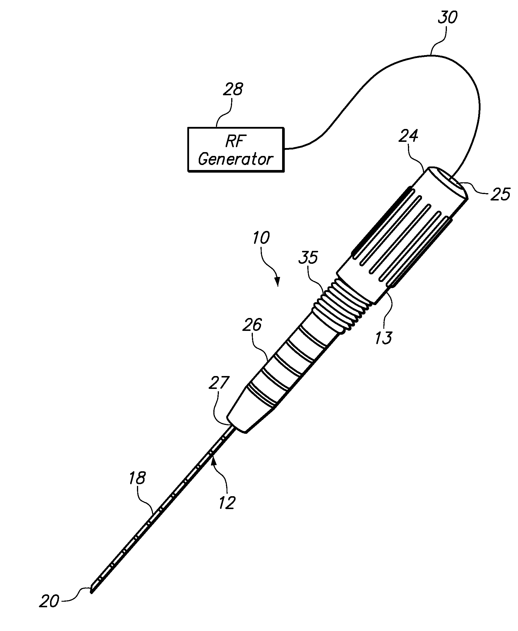
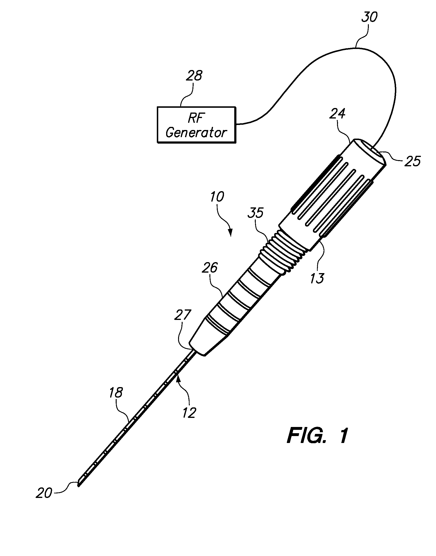
[0021]FIG. 1 depicts an array advancing device 10, constructed in accordance with one embodiment of the invention. The array advancing device 10 is attached to a tissue ablation probe 12 (best seen in FIGS. 2-4). The ablation probe 12 is connected via a RF cable 30 to a generator 28, which supplies RF energy to an array 22 of elongate electrode elements 41 (seen in FIGS. 3-4) that are deployable from a distal end opening 20 of a tissue-piercing delivery cannula 18 that extends distally from the probe 12.

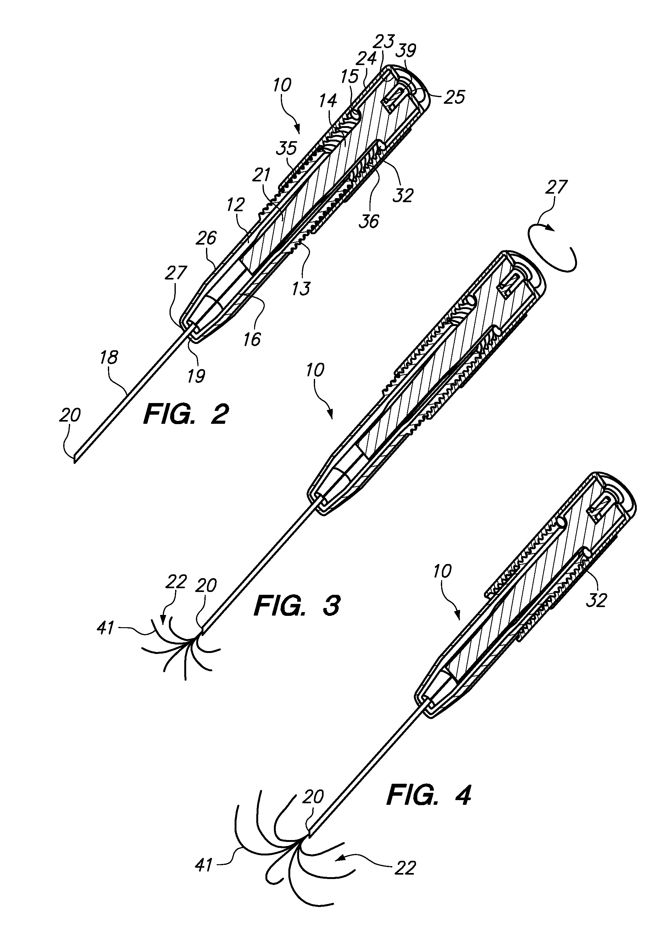
[0022]With reference also to FIG. 2, the array advancing device 10 comprises a generally cylindrical (i.e., barrel-shaped) housing 13 that defines an interior chamber 21 sized for receiving the ablation probe 12. The housing 13 includes a proximal housing section 24 that is threadably coupled and moveably relative to a distal housing section 26. The proximal housing section 24 includes a proximal end opening 25 sized to allow the RF cable 30 to be connected to a proximal end connecto...


PUM


Abstract

An array advancing device that attaches to a tissue ablation probe comprises a housing sized for receiving the handle and reciprocating plunger of the ablation probe, the housing having a proximal section configured to engage the plunger, and a distal section configured to engage the handle, the proximal housing section being controllably moveable relative to the distal housing section to thereby controllably move the plunger relative to the handle.

Description

RELATED APPLICATION DATA[0001]The present application claims the benefit under 35 U.S.C. § 119 to U.S. provisional patent application Ser. No. 60 / 882,128, filed Dec. 27, 2006. The foregoing application is hereby incorporated by reference into the present application in its entirety.FIELD OF INVENTION[0002]The present invention relates to systems and methods for ablating tissue in interior regions of the human body and, more particularly, to a device for more precise and controlled deployment of elongated electrode elements of an radio frequency (RF) electrode array probe.BACKGROUND[0003]The delivery of radio frequency (RF) energy to target regions of tissue is known for a variety of purposes of particular interest to the present invention. For example, U.S. Pat. Nos. 5,868,740, 6,379,353, 6,468,273, 6,889,089, U.S. Patent Application Publication No. 2005-0137659, and PCT application WO 96 / 29946 describe some of such tissue ablation systems.[0004]The delivery of RF energy to target r...

Claims


Application Information

Patent Timeline
Patent Type & Authority Applications(United States)
IPC IPC(8): A61B18/14
CPCA61B18/1477A61B2018/0016A61B2018/1861A61B2018/00214A61B2018/00952A61B2018/00196
Inventor RIOUX, ROBERT F.BEAN, JEFFERY V.
Owner BOSTON SCI SCIMED INC
Why Eureka
Try Eureka