
Egr control apparatus and method for internal combustion engine

a control apparatus and internal combustion engine technology, applied in the direction of machines/engines, process and machine control, output power, etc., can solve the problems of engine output, drivability, combustion efficiency reduction, etc., and achieve good fuel efficiency, reduce pumping loss, and improve combustion efficiency

Inactive Publication Date: 2008-07-03
HONDA MOTOR CO LTD
View PDF9 Cites 21 Cited by
  • Summary
  • Abstract
  • Description
  • Claims
  • Application Information

AI Technical Summary

Benefits of technology

The present invention provides an EGR control apparatus and method for an internal combustion engine that can improve combustion efficiency, engine output, and drivability by controlling the amount of exhaust gases released from a cylinder. The apparatus includes an EGR control system that can switch between a plurality of combustion modes and calculate the target EGR amount based on the selected combustion mode. The target EGR amount is set by combining the internal EGR amount and the external EGR amount, which is determined by the target in-cylinder gas temperature. The EGR control system can control the internal and external EGR amounts to achieve the target EGR amount by driving the internal and external EGR devices. The technical effects of this invention include improved combustion efficiency, increased engine output, and reduced emissions.

Problems solved by technology

As a result, in order to avoid knocking, an ignition timing retard control and the like are obliged to be executed, possibly resulting in a reduction in combustion efficiency, engine output, and drivability.

Method used


Image

  • Egr control apparatus and method for internal combustion engine
  • Egr control apparatus and method for internal combustion engine
  • Egr control apparatus and method for internal combustion engine

Examples


Embodiment Construction

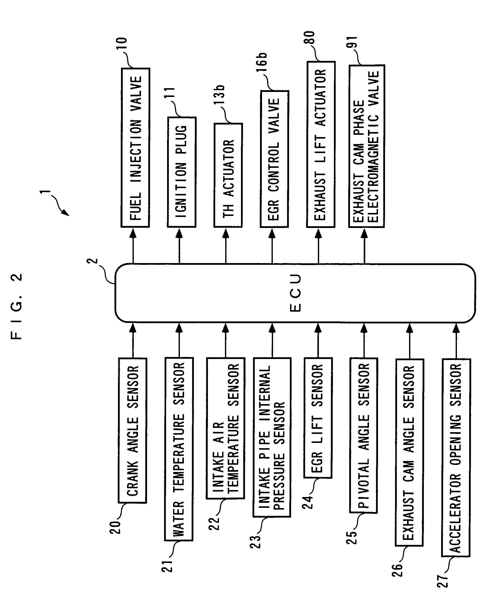
[0033]In the following, an EGR control apparatus for an internal combustion engine according to one embodiment of the present invention will be described with reference to the drawings. As shown in FIG. 2, this EGR control apparatus 1 comprises an ECU 2, and this ECU 2 executes a variety of control processes such as an EGR control process in accordance with an operating condition of the internal combustion engine (hereinafter referred to as the “engine”) 3, as will be later described.

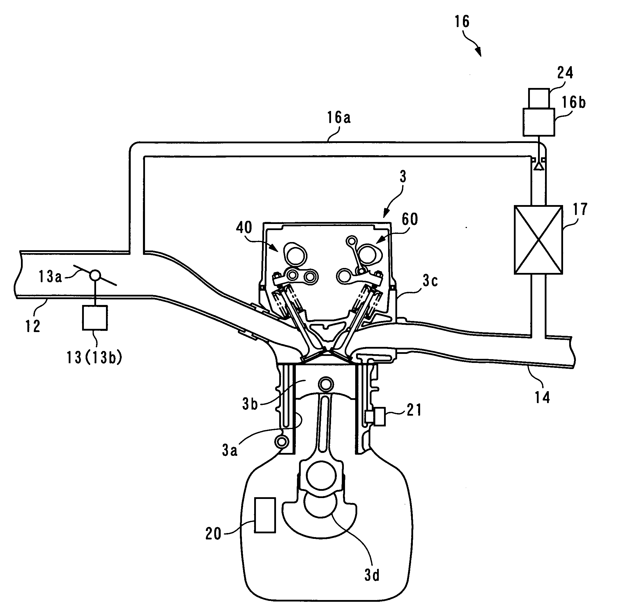
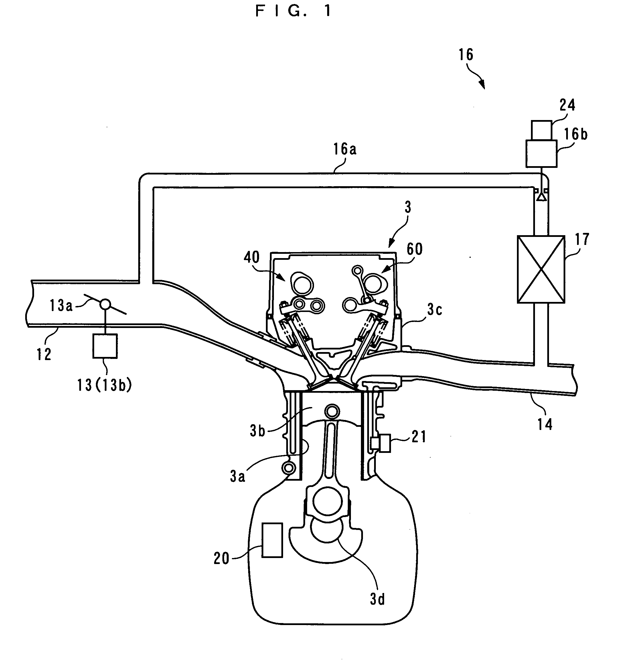
[0034]As shown in FIGS. 1 and 3, the engine 3 is an in-line four-cylinder type four cycle gasoline engine which has four sets of cylinders 3a and pistons 3b (only one set of which is shown) and is equipped in a vehicle (not shown), and a combustion chamber 3e is formed between the piston 3b of each cylinder 3a and a cylinder head 3c.

[0035]The engine 3 comprises a pair of intake valves 4, 4 (only one of which is shown) provided for each cylinder 3a, a pair of exhaust gas valves 7, 7 (only one of which i...


PUM


Abstract

An EGR control apparatus and method for an internal combustion engine which burns an air-fuel mixture with self ignition in addition to a flame propagation combustion, are provided for improving the combustion efficiency, engine output, drivability, and exhaust gas characteristics in an internal combustion engine which involves a self ignition combustion of an air-fuel mixture in addition to a flame propagation combustion. The EGR control apparatus comprises an ECU which selects one of a stratified self ignition mode, a stratified flame propagation combustion mode, and a homogeneous flame propagation combustion mode, sets a total target EGR amount and a target in-cylinder gas temperature in accordance with the selected combustion mode, calculates a target internal EGR amount in accordance with the value, calculates a target external EGR amount by subtracting the target internal EGR amount from the total target EGR amount, and controls the internal EGR amount and the external EGR amount to be the target internal EGR amount and the target external EGR amount, respectively, by driving three mechanisms.

Description

BACKGROUND OF THE INVENTION[0001]1. Field of the Invention[0002]The present invention relates to an EGR control apparatus and method for an internal combustion engine for burning an air-fuel mixture with self ignition while auxiliary using a spark ignition.[0003]2. Description of the Prior Art[0004]Conventionally, as an EGR control apparatus for an internal combustion engine, one described, for example, in Laid-open Japanese Patent Application No. 11-210539 is known. This internal combustion engine is of a type which can be operated by switching between a self ignition combustion mode for burning an air-fuel mixture with self ignition while auxiliary using a spark ignition and a flame propagation combustion mode for burning an air-fuel mixture with flame propagation using a spark ignition. This internal combustion engine comprises an EGR control valve for controlling the amount of exhaust gases recirculated from an exhaust passage to an intake passage, and a valve timing mechanism f...

Claims


Application Information

Patent Timeline
Patent Type & Authority Applications(United States)
IPC IPC(8): F01N9/00F02B47/08F01L1/04F01L1/344F02M25/07F02D13/02F02D21/08
CPCF01L1/185Y02T10/18F01L1/344F01L13/0063F01L2001/0537F01L2105/00F01L2800/00F01L2800/10F01L2820/02F02D13/0265F02D21/08F02M25/0731F02M25/0756F02M25/0772F01L1/20F02M26/28F02M26/48F02M26/53F01L2305/00Y02T10/12
Inventor ITOGA, CHIHOOGAWA, KENKITAMURA, TORUSHINOHARA, TOSHINARI
Owner HONDA MOTOR CO LTD
Learn More