Management method for reducing utilization rate of random access memory (RAM) used in flash memory

Active Publication Date: 2008-07-03
GENESYS LOGIC INC
View PDF4 Cites 104 Cited by
  • Summary
  • Abstract
  • Description
  • Claims
  • Application Information

AI Technical Summary

Benefits of technology

[0019]One objective of the present invention is to provide a management method for reducing the utilization rate of random access memory (RAM) while reading data from or writing data to the flash memory so that the requirement of the random access memory is decreased to be applicable to the portable device having limited random access memory (RAM).
[0020]Another objective of the present invention is to provide a management method for reducing the utilization rate of random access memory while reading data from or writing data to the flash memory. If the bad blocks in the flash memory exceeds a predetermined threshold amount, e.g. twelve bad blocks in a physical flash memory plane, the management method is capable of maintaining the data-accessing reliable and correct.
[0021]According to the objectives, the present invention sets forth a management method for reducing the utilization rate of random access memory while reading data from or writing data to the flash memory. A physical memory set is constructed from a plurality of physical memory blocks in the flash memory. A

Problems solved by technology

However, considering the manufacturing cost of the flash memory, the capacity of the random access memory (RAM) is limited.
The disadvantage is that it takes a lot of time to make on-demand fetching or scan the flash memory for constructing different partial mapping tables when the addresses accessed by the host are variable from time to time.
Moreover, such situation becomes more severe if the capacity of the flash memory is increased.
Additionally, with

Method used


Image

  • Management method for reducing utilization rate of random access memory (RAM) used in flash memory
  • Management method for reducing utilization rate of random access memory (RAM) used in flash memory
  • Management method for reducing utilization rate of random access memory (RAM) used in flash memory

Examples


Example

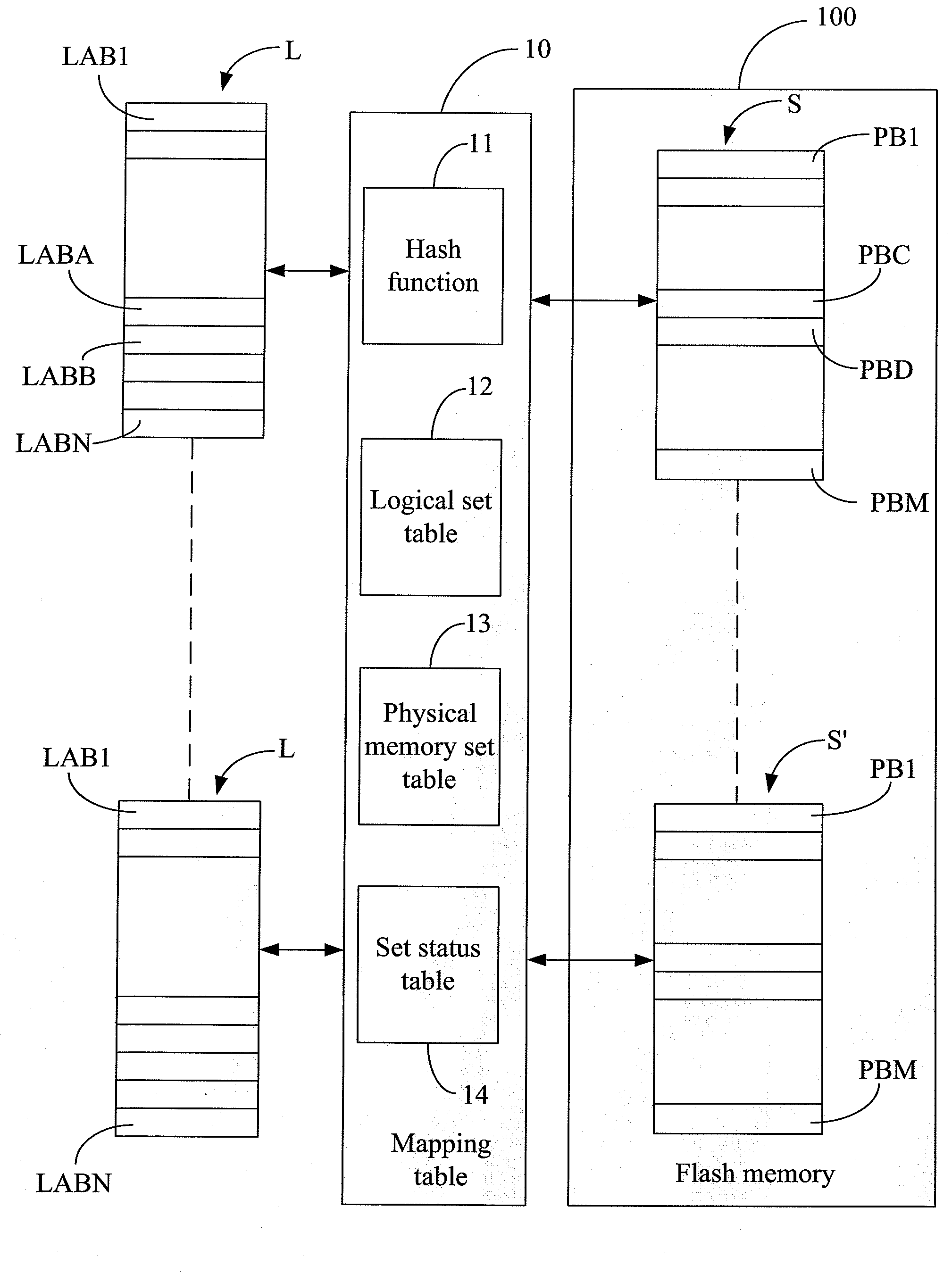
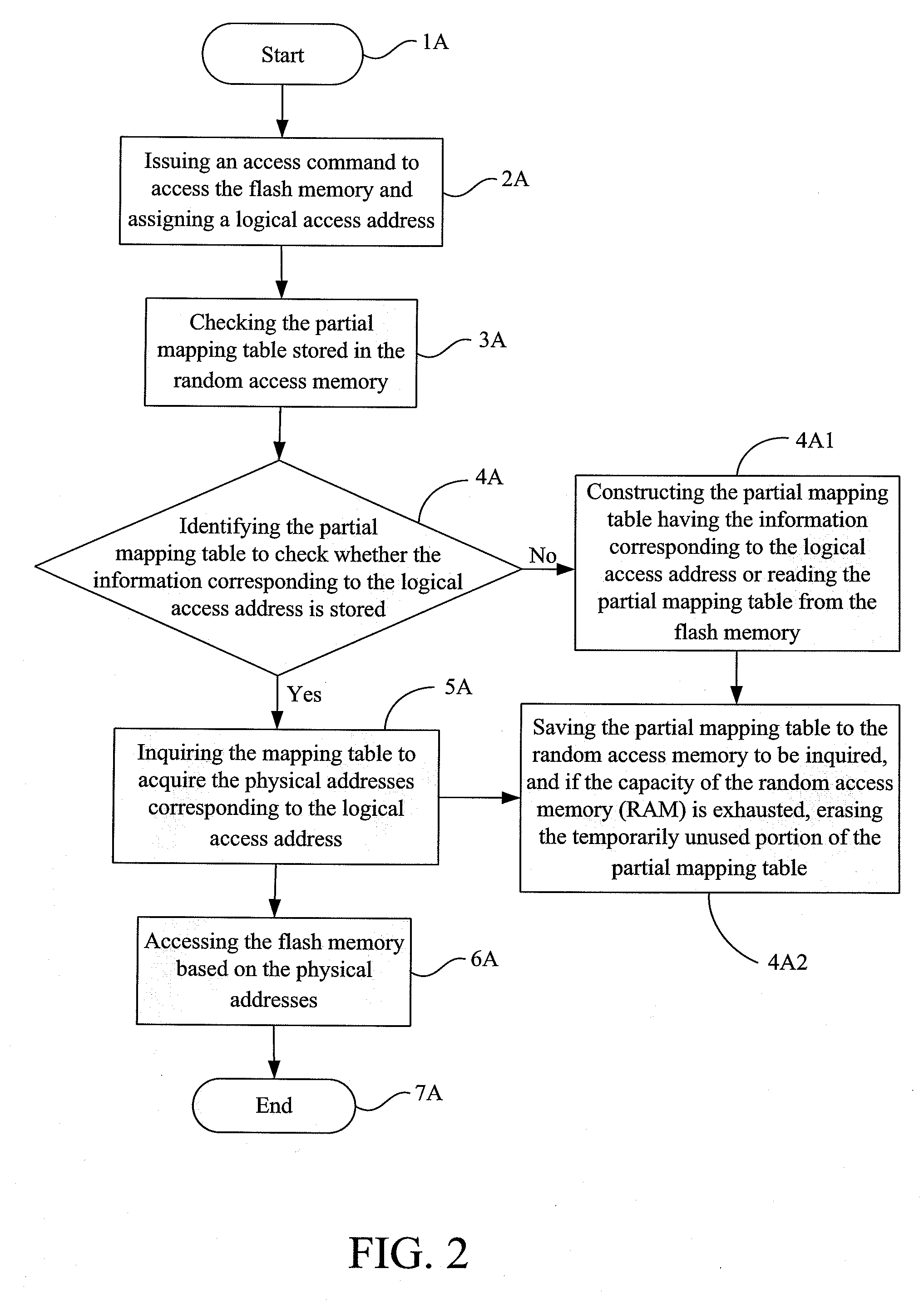
[0036]Please refer to FIG. 4. FIG. 4 illustrates an architecture definition view of a management method used in flash memory for reducing the utilization rate of random access memory (RAM) according to one embodiment of the present invention. The physical memory set “S” or “S′” includes the amount “m” of physical memory blocks “PB1” to “PBM” in the flash memory 100, and the logical set “L” or “L′” includes the amount “n” of logical blocks “LAB1” to “LABN”. The data in the same logical set are stored in the same physical memory set wherein the amount “n” is smaller than or equal to the amount “m”. The data stored in each of the logical blocks “LAB1” to “LABN” are not necessarily stored in a specific number of physical memory blocks.

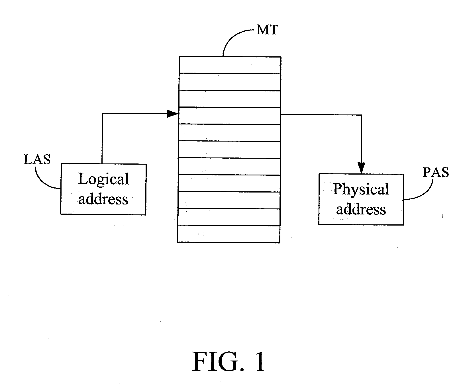
[0037]That is, while writing or updating a logical block “LABA”, the logical block address (LBA) corresponds to the physical memory set “S” after inquiring a mapping table 10. The mapping table 10 includes a hash function 11, a logical set table 12, a phys...


PUM


Abstract

A management method for reducing the utilization rate of random access memory (RAM) while reading data from or writing data to the flash memory is disclosed. A physical memory set is constructed from a plurality of physical memory blocks in the flash memory. A logical set is constructed from a plurality of logical blocks wherein the data stored in the logical set are stored in the physical memory set. Further, the data stored in each of the logical blocks are stored in one number of physical memory blocks. A mapping table is constructed and includes a hash function, a logical set table, a physical memory set table, and a set status table for managing the relationship among the physical memory sets, physical memory blocks, and logical blocks while reading data from or writing data to the flash memory. Further, the management method operates and maintains the physical memory sets, the physical memory blocks, and the logical blocks at a set level so that the utilization rate of random access memory is reduced to decrease the access capacity of the random access memory while operating the physical memory blocks and the logical blocks of the flash memory.

Description

FIELD OF THE INVENTION[0001]The present invention relates to a method for managing the utilization rate of memory, and more particularly to a management method for reducing the utilization rate of random access memory (RAM) to decrease the access capacity of the random access memory while reading data from or writing data to the flash memory.BACKGROUND OF THE INVENTION[0002]Regarding the technical field of the conventional flash memory, the architecture of flash memory includes a flash memory chip having a plurality of physical flash memory planes. Further, one of physical flash memory planes is composed of hundreds of flash memory blocks wherein the memory capacity of a flash memory block is in a range from 16 KB to 128 KB.[0003]Please refer to FIG. 1. FIG. 1 is a management architecture of the conventional flash memory. There are many kinds of management methods of the flash memory. However, while implementing the management methods, it is required to establish a mapping table (ab...

Claims


Application Information

Patent Timeline
IPC IPC(8): G06F12/02
CPCG06F12/0246
Inventor CHU, YUAN-SHENGHSIEH, JEN-WEICHANG, YUAN-HAOKUO, TEI-WEIYANG, CHENG-CHIH
Owner GENESYS LOGIC INC
Why Eureka
Try Eureka