Vehicle exhaust system structure

a technology of exhaust system and exhaust pipe, which is applied in the direction of mechanical equipment, machines/engines, transportation and packaging, etc., can solve the problem of large force applied to the bend portion of the exhaust pip

Inactive Publication Date: 2008-07-10
TOYOTA JIDOSHA KK
View PDF0 Cites 11 Cited by
  • Summary
  • Abstract
  • Description
  • Claims
  • Application Information

AI Technical Summary

Benefits of technology

[0008]A first aspect of the present invention provides a vehicle exhaust system structure for discharging exhaust gases of an internal combustion engine, which is transversely installed in a front part of a vehicle body, from a rear part of the vehicle body, the vehicle exhaust system structure comprising: a first catalytic device, a second catalytic device, an exhaust heat recovery unit and a silencer which are disposed sequentially in that order from an upstream side in an exhaust gas flow direction; a first exhaust pipe which connects the second catalytic device to the exhaust heat recovery unit; a second exhaust pipe which includes a portion extending in a direction intersecting a vehicle front-rear direction, and which connects the exhaust heat recovery unit, which is disposed to be offset in a vehicle width direction, to the silencer; a suspension unit which suspends at least part of the exhaust system elements including the exhaust heat recovery unit, the second exhaust pipe, and the silencer, relative to the vehicle body, on a downstream side in an exhaust gas flow direction relative to the first exhaust pipe; and a vibration cut-off mechanism which is provided at the first exhaust pipe and permits a relative displacement betwee

Problems solved by technology

In the above-mentioned related art, however, it is feared that a large magnitude of force is applied to the bend portion of the exhaust pipe wh

Method used


Image

  • Vehicle exhaust system structure
  • Vehicle exhaust system structure
  • Vehicle exhaust system structure

Examples


Embodiment Construction

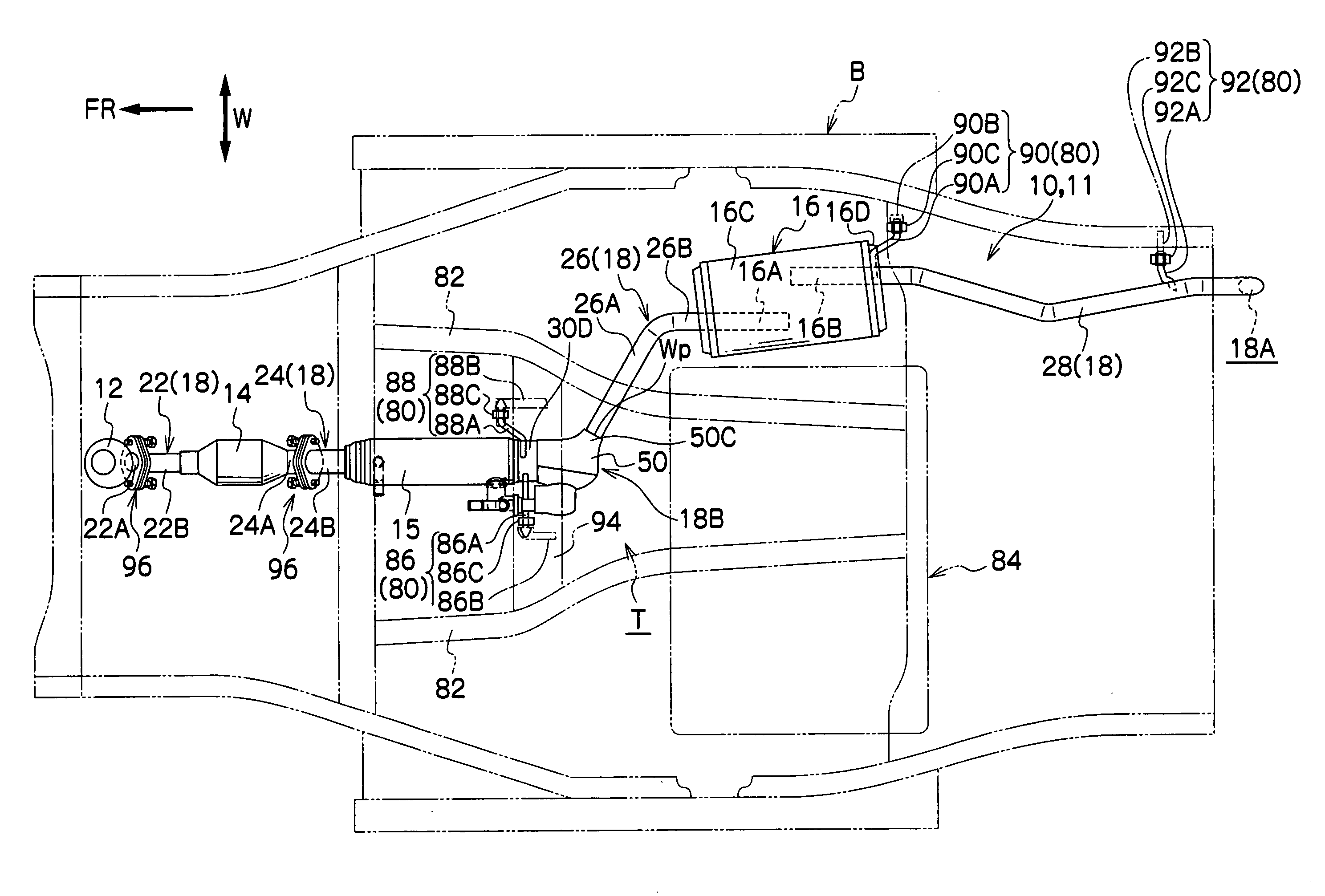
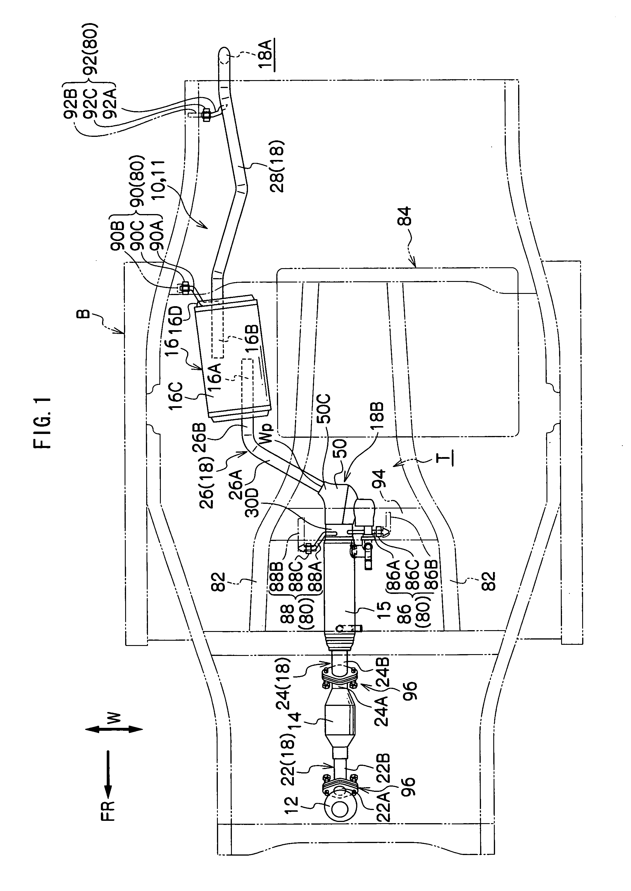
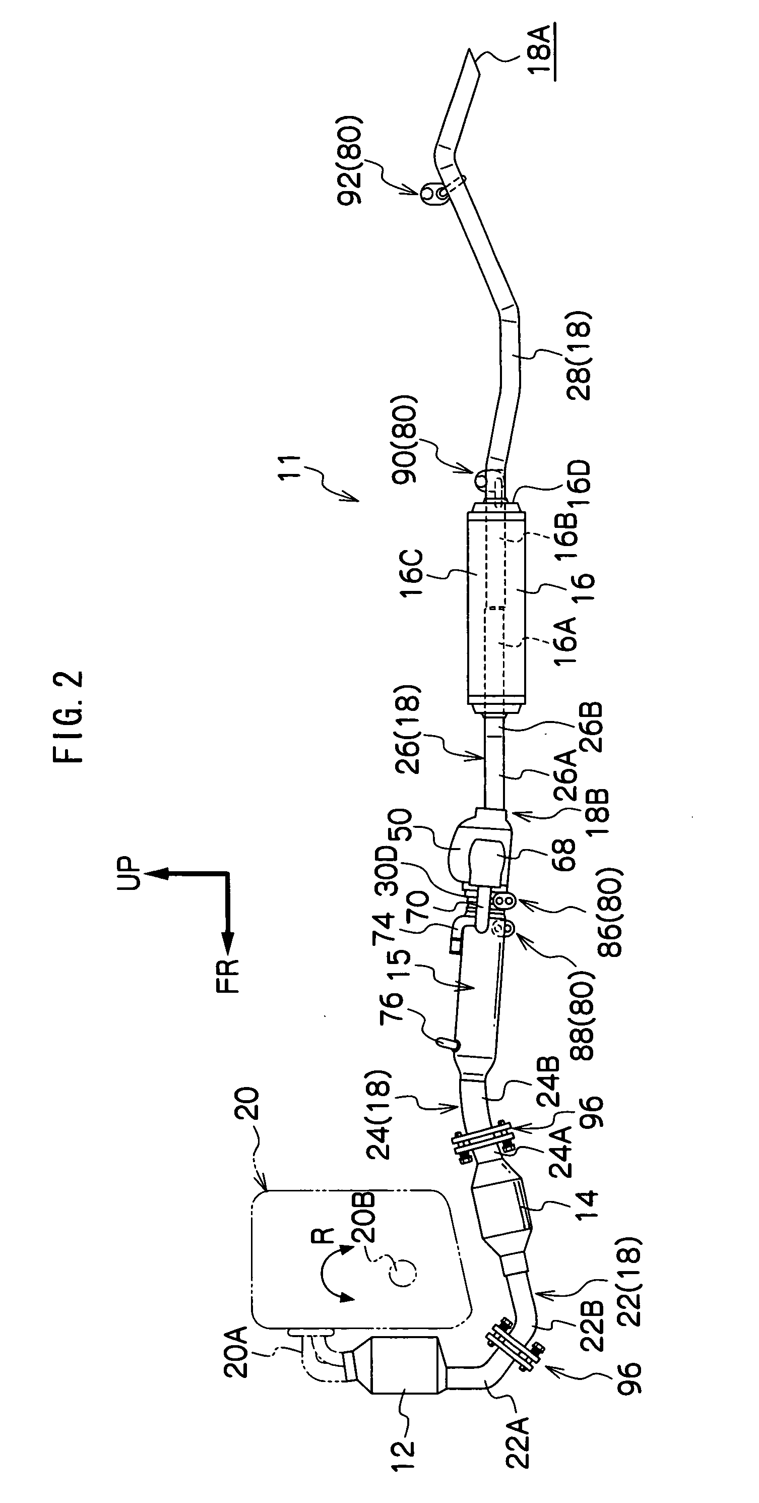
[0021]Hereinbelow, an example of an exemplary embodiment of the present invention will be described in detail with reference to the drawings.

[0022]Firstly, an overall configuration of an exhaust system 11 to which a vehicle exhaust system structure 10 is applied will be schematically described, next, an exhaust system heat exchanger 15 which makes up the vehicle exhaust system structure 10 will be described, and thereafter, a support structure of the exhaust system 11 relative to a vehicle body will be described which constitutes a main part of the present invention in the vehicle exhaust system structure 10. Note that in the following description, when such words as upstream and downstream are simply used, they are to denote upstream and downstream of an exhaust gas flow direction. In addition, an arrow FR, arrow UP and arrow W which are shown in the respective drawings are to denote, respectively, front side (running direction) in a vehicle front-rear direction, upper side in a ve...


PUM


Abstract

A vehicle exhaust system structure is obtained which can protect well a bend portion of an exhaust pipe. A vehicle exhaust system structure 10 is intended to discharge exhaust gases of a front-engine front-drive vehicle with a transverse engine from a rear part of a vehicle body and is applied to an exhaust system 11 which is configured such that a first catalytic converter 12, a second catalytic converter 14, an exhaust system heat exchanger 15 and a muffler 16 are disposed sequentially in that order from an upstream side in an exhaust gas flow direction. In the exhaust system 11, a heat exchanger to muffler exhaust pipe 26 which connects the exhaust system heat exchanger 15 to the muffler 16 has an inclined portion 26A, and a portion of the exhaust system 11 which lies further rearwards than the exhaust system heat exchanger 15 is suspended from the vehicle body by a suspension unit 80. Provided on a catalytic converter to heat exchanger exhaust pipe 24 which connects the second catalytic converter 14 to the exhaust system heat exchanger 15 is a ball joint 96 which permits a relative displacement between the second catalytic converter 14 and the exhaust system heat exchanger 15.

Description

CROSS-REFERENCE TO RELATED APPLICATION[0001]This application claims priority under 35 USC 119 from Japanese Patent Application, No. 2007-1581, the disclosure of which is incorporated by reference herein.BACKGROUND OF THE INVENTION[0002]1. Field of the Invention[0003]The present invention relates to a vehicle exhaust system structure for an internal combustion engine which is installed transversely in a front part of a vehicle body of, for example, a front-engine front-drive vehicle, and more particularly to a vehicle exhaust system structure which includes an exhaust heat recovery unit for recovering exhaust heat.[0004]2. Description of the Related Art[0005]As is disclosed in, for example, Japanese Patent Application Laid-Open (JP-A) Nos. 10-196358 and 2004-190610, in an exhaust system which is connected to a transverse internal combustion engine and in which a catalytic converter, a sub-muffler and a main muffler are disposed directly in that order from an upstream side of an exhau...

Claims


Application Information

Patent Timeline
IPC IPC(8): F01N3/10B60K13/04F01N3/24F01N5/02F01N13/00F01N13/08F01N99/00
CPCB60K13/04F01N3/2885F01N13/08F01N13/009F01N13/1816F01N13/1822F01N13/0093F01N13/1811Y02A50/20F01N3/24F01N3/28
Inventor MABUCHI, TOMOKINISHINO, HISASHI
Owner TOYOTA JIDOSHA KK
Why Eureka
Try Eureka