Gas well de-watering apparatus and method

a technology of gas wells and dewatering equipment, which is applied in the direction of fluid removal, non-positive displacement pumps, borehole/well accessories, etc., can solve the problems of insufficient pressure to produce to the surface, the level of accumulating liquids begins to rise, etc., and achieves the effect of reducing the density of production fluids and reducing tubing pressur

Inactive Publication Date: 2008-07-10
ALTECH INDS
View PDF10 Cites 7 Cited by
  • Summary
  • Abstract
  • Description
  • Claims
  • Application Information

AI Technical Summary

Benefits of technology

[0020]During production of the well, formation liquids accumulate at the bottom of the well bore. The level of accumulating liquids begins to rise when the formation pressure becomes inadequate to produce these liquids to the surface. The accumulating liquids eventually rise above the lower end of the tubing string, effectively trapping formation gas in the annular space beneath the packer and between the production casing and the tubing string. Gas from the formation continues to rise through the accumulating liquids and into this annular space. The formation gas accumulating in the annulus exerts a downward pressure on the rising formation liquids. However, the pressure is not adequate to produce to the surface both the accumulated fluid beneath the trapped gas and within the tubing string. Nonetheless, the pressure of the trapped gas becomes sufficient in time to move the column of accumulating liquid downward toward the pressure regulator contained inside of the carrier sub disposed within the tail pipe. The carrier sub allows direct communication between the trapped gas and the internal pressure regulator. As the gas passes into the pressure regulator, the regulator senses the pressure differential between the outside and inside of the tubing string. If the pressure differential is greater than a preset value then the regulator directs the gas into the production tubing string thereby lowering the density of production fluids inside of the tubing string, decreasing the tubing pressure, and producing to the surface the fluids within the tubing string above the carrier sub. This initiates the systematic process of removing liquid build-up beneath the packer and across the perforated zones of the well.
[0021]Depending upon the length of the perforated zones, additional carrier subs with internal pressure regulators are spaced out along the tubing string allowing deeper points of gas injection, and consequently, more fluid build-up below the packer to be produced from the well bore. The deeper gas injection points also create lower “flowing bottom-hole” pressures from the reservoir, which allows the well to be produced at higher rates using the existing formation pressure. As a result, the well is able to produce formation fluids for a longer period of time and without surface intervention.

Problems solved by technology

The level of accumulating liquids begins to rise when the formation pressure becomes inadequate to produce these liquids to the surface.
However, the pressure is not adequate to produce to the surface both the accumulated fluid beneath the trapped gas and within the tubing string.

Method used


Image

  • Gas well de-watering apparatus and method
  • Gas well de-watering apparatus and method
  • Gas well de-watering apparatus and method

Examples


Embodiment Construction

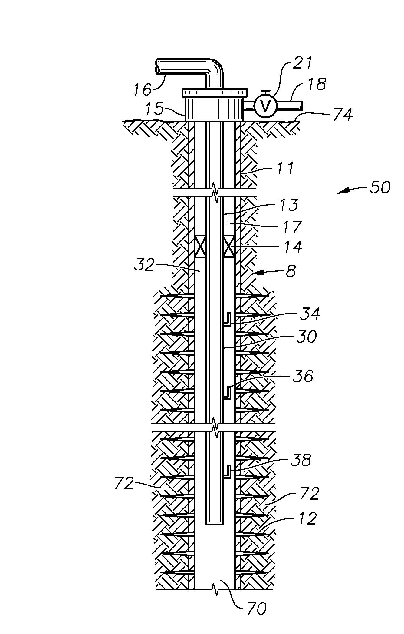
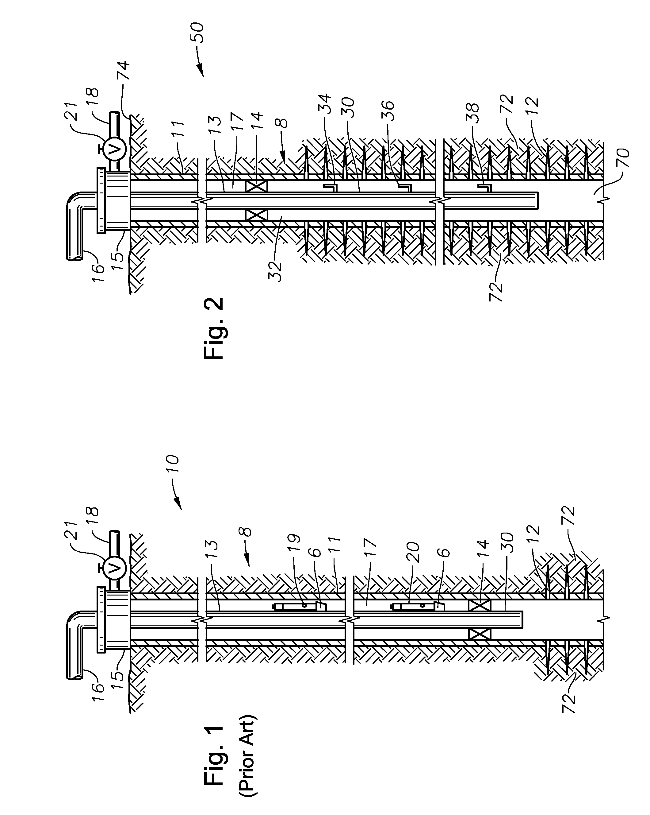
[0027]The preferred embodiment of the invention alleviates one or more of the deficiencies described in the prior art and incorporates one or more of the objects previously identified. Referring now to the drawings, FIG. 1 illustrates a prior art well arrangement 10 employing artificial gas-lift technologies. A well bore 8 is lined with well casing 11 that, during well completion is perforated at 12 so that oil, gas, and other formation fluids from a subsurface earth production zone 72 can enter through casing 11. Production tubing string 13 extends from the surface down to packer 14, which is set above perforations 12 so that the oil, gas, and other formation fluids must flow up tubing string 13 to the surface 74, through casing head 15 and into production line 16.

[0028]A series of spaced pressure regulating valves 19, 20 are mounted on the tubing string 13 above packer 14 using conventional mandrels 6, with the lowermost pressure regulating valve 20 being arranged to control the i...


PUM


Abstract

A system and method for systematically and economically recovering formation liquids from the bottom of a petroleum well are disclosed. In a preferred embodiment, the system and method are passive in that they utilize the existing formation pressure of the well to remove fluid build-up across the perforations of the well bore in a manner that is completely free from surface control. The system is comprised of strategically placed carrier subs with installed pressure regulating devices. These carrier subs are regularly spaced below the production packer, along the tail pipe section of the production tubing string and facing the perforated intervals of the well bore. The pressure of the trapped formation gas above the accumulating formation liquid is insufficient to remove all of the formation liquid within the entire length of the tubing string 13. However, an open pressure regulating device mounted on the tailpipe section of the tubing string allows a smaller portion of the formation liquid within the tubing string to be produced to the surface using the existing formation pressure. By systematically removing portions of the formation liquid from within the tubing string using the regularly spaced pressure regulating valves, the formation fluid build-up across the perforations is eliminated, and the petroleum well is able to produce at higher rates and for a longer period without intervention.

Description

BACKGROUND OF THE INVENTION[0001]1. Field of the Invention[0002]This invention relates generally to the extraction of petroleum fluids from subsurface formations. More specifically, this invention relates to an apparatus and method for eliminating fluid build-up across the perforations within subsurface wells in order to facilitate greater extraction of petroleum fluids using the natural formation pressure as the primary driving force.[0003]2. Description of the Prior Art[0004]Production costs are a critical consideration in the extraction of the petroleum fluids from subsurface formations. The goal, of course, is to extract petroleum fluid from the subsurface formation at the least expense. The subsurface formation has a naturally occurring pressure that facilitates the removal of petroleum fluids to the surface. Petroleum wells that produce oil and / or gas primarily using the natural formation pressure are generally the least expensive to operate. However, the formation pressure de...

Claims


Application Information

Patent Timeline
Patent Type & Authority Applications(United States)
IPC IPC(8): E21B43/12
CPCE21B43/122E21B43/13
Inventor BRINK, DONALD J.
Owner ALTECH INDS
Why Eureka
Try Eureka