Step-by-step motor able to carry out up-and-down motion

a step-by-step motor and up-and-down technology, which is applied in the direction of dynamo-electric machines, instruments, master clocks, etc., can solve the problems of b>11/b> falling off and the effect of losing the effect of bonding agents

Inactive Publication Date: 2008-07-10
HUANG HSIU MING
View PDF7 Cites 59 Cited by
  • Summary
  • Abstract
  • Description
  • Claims
  • Application Information

AI Technical Summary

Benefits of technology

[0006]The objective of this invention is to offer a step-by-step motor able to carry out up-and-down motion, able to be assembled conveniently and quickly.

Problems solved by technology

However, the connecting base 11 of the step-by-step motor 1 is fixed on the housing 10 by means of the bonding agent; therefore, after used for a long period of time, the bonding agent may lose its efficacy and the connecting base 11 is likely to fall off.

Method used


Image

  • Step-by-step motor able to carry out up-and-down motion
  • Step-by-step motor able to carry out up-and-down motion
  • Step-by-step motor able to carry out up-and-down motion

Examples


Embodiment Construction

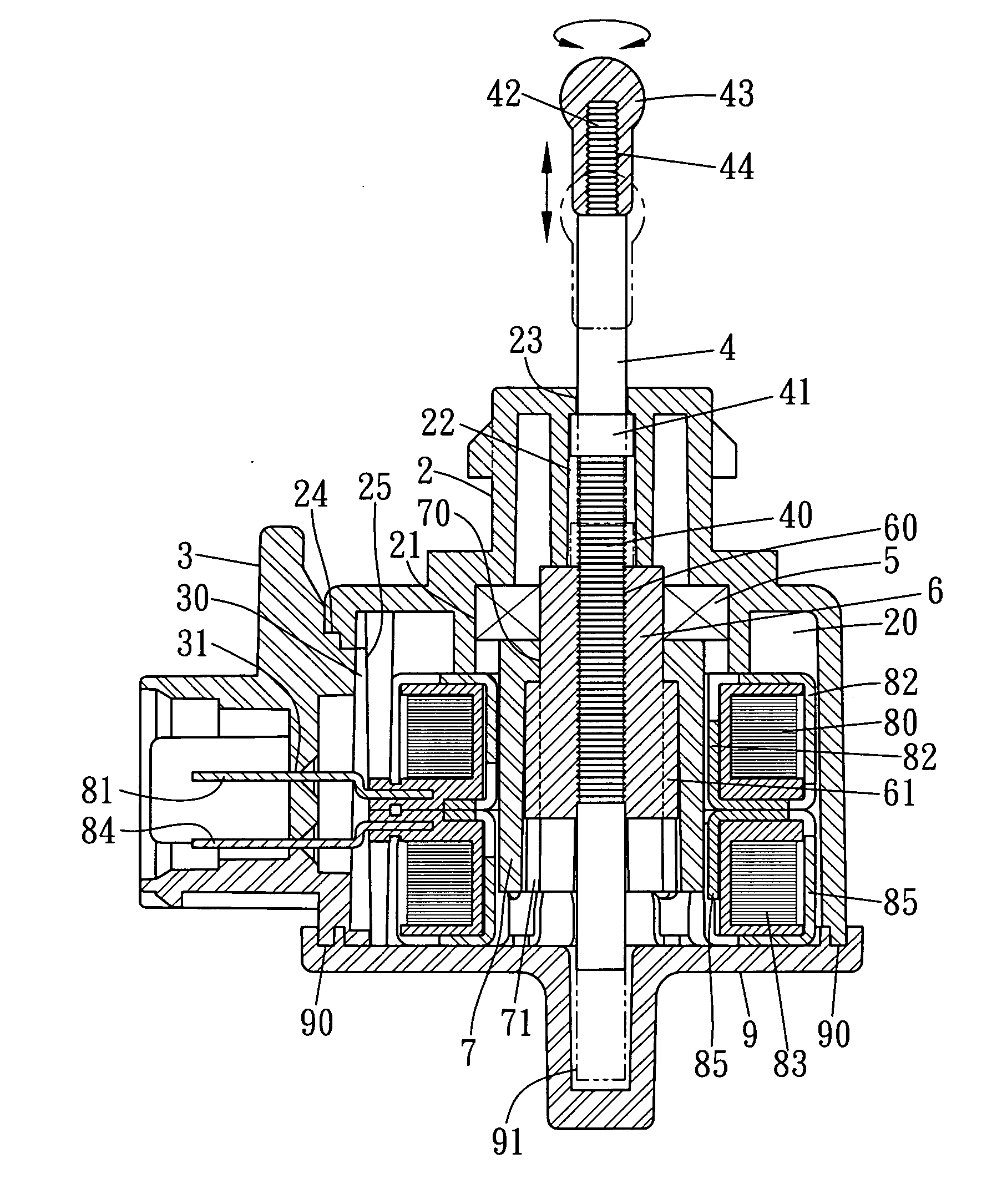
[0015]A preferred embodiment of a step-by-step motor able to carry out up-and-down motion in the present invention, as shown in FIGS. 4, 5 and 6, includes a housing 2, a connecting base 3, a top rod 4, a bearing 5, a connecting member 6, a magnet 7, a right-handed coil 80, a reverse coil 83 and a bottom cover 9 combined together.

[0016]The housing 2 is formed in the interior with an accommodating chamber 20 provided inside with a recessed chamber 21 with a rectangular slot 22 having its upper side bored with an insert hole 23. The housing 2 further has one sidewall bored with an opening 24 having its inner wall disposed with slide grooves 25.

[0017]The connecting base 3 to be assembled on one sidewall of the housing 10 has the peripheral edge of one sidewall disposed with a slide rail 30 and its interior bored with a plurality of connecting holes 31.

[0018]The top rod 4 to be inserted through the insert hole 23 of the housing 2 has the section near its lower end formed with male thread...


PUM


Abstract

A step-by-step motor able to carry out up-and-down motion includes a housing, a connecting base, a top rod, a bearing, a connecting member, a magnet, a right-handed coil, a reverse coil and a bottom cover combined together. The housing has one side bored with an opening and its inner wall bored with a slide groove, and the connecting base has one outer wall formed with a slide rail for combining the connecting base on the outer wall of the housing. The bottom cover is provided with an annular recess for engaging the bottom edge of the housing, and then the bottom cover and the housing are firmly combined together by supersonic welding. By so designing, the step-by-step motor can be assembled conveniently, quickly and stably.

Description

BACKGROUND OF THE INVENTION[0001]1. Field of the Invention[0002]This invention relates to a step-by-step motor able to carry out up-and-down motion, particularly to one assembled by having the slide rails of a combining base respectively inserted in the slide grooves of a housing and by supersonic welding, able to be assembled conveniently and stably.[0003]2. Description of the Prior Art[0004]The headlamp of an automobile is usually installed with a step-by-step motor for adjusting the radiating height of the headlamp. A conventional step-by-step motor, as shown in FIGS. 1, 2 and 3, includes a housing 10 provided with a positioning post 100 in the interior, and having one sidewall bored with an opening 101 and its upper edge formed with a plurality of positioning projections 102 spaced apart and extending upward. A connecting base 11 is secured on the outer wall of the opening 101 of the housing 10 by means of a bonding agent, with its topside disposed with a plurality of posts 110....

Claims


Application Information

Patent Timeline
Patent Type & Authority Applications(United States)
IPC IPC(8): H02K37/00H02K5/04H02K5/16
CPCH02K3/525H02K5/08H02K5/15H02K37/14H02K5/225H02K7/06H02K5/1672
Inventor HUANG, HSIU-MING
Owner HUANG HSIU MING
Why Eureka
Try Eureka