
Digital Current Mode Controller

a digital current and mode controller technology, applied in the direction of ignition automatic control, pulse technique, instruments, etc., can solve the problems of not being attractive to mainstream high-frequency low-to-medium power dc-dc applications, quantization effects in the combined current and voltage loop have not been addressed so far, and achieve the effect of simple digital controller

Inactive Publication Date: 2008-07-10
UNIV OF COLORADO THE REGENTS OF
View PDF5 Cites 70 Cited by
  • Summary
  • Abstract
  • Description
  • Claims
  • Application Information

AI Technical Summary

Benefits of technology

[0008]A digital average current-mode controller architecture based on a current analog-to-digital (A/D) converter and a digital controller is provided. In one embodiment, for example, the digital average current-mode controller architecture may

Problems solved by technology

These approaches have relied on relatively high-resolution current A / D converters and more complex processing, which may not be attractive for mainstream high-frequency low-to-medium power DC-DC applications where a small-size, low-cost controller would be the most practical solution.
Furthermore, quantization effects in the combined current and voltage loops have not been addressed so far.

Method used


Image

  • Digital Current Mode Controller
  • Digital Current Mode Controller
  • Digital Current Mode Controller

Examples


Embodiment Construction

[0024]Switched-Mode DC-DC Converter with a Digital Current Mode Controller

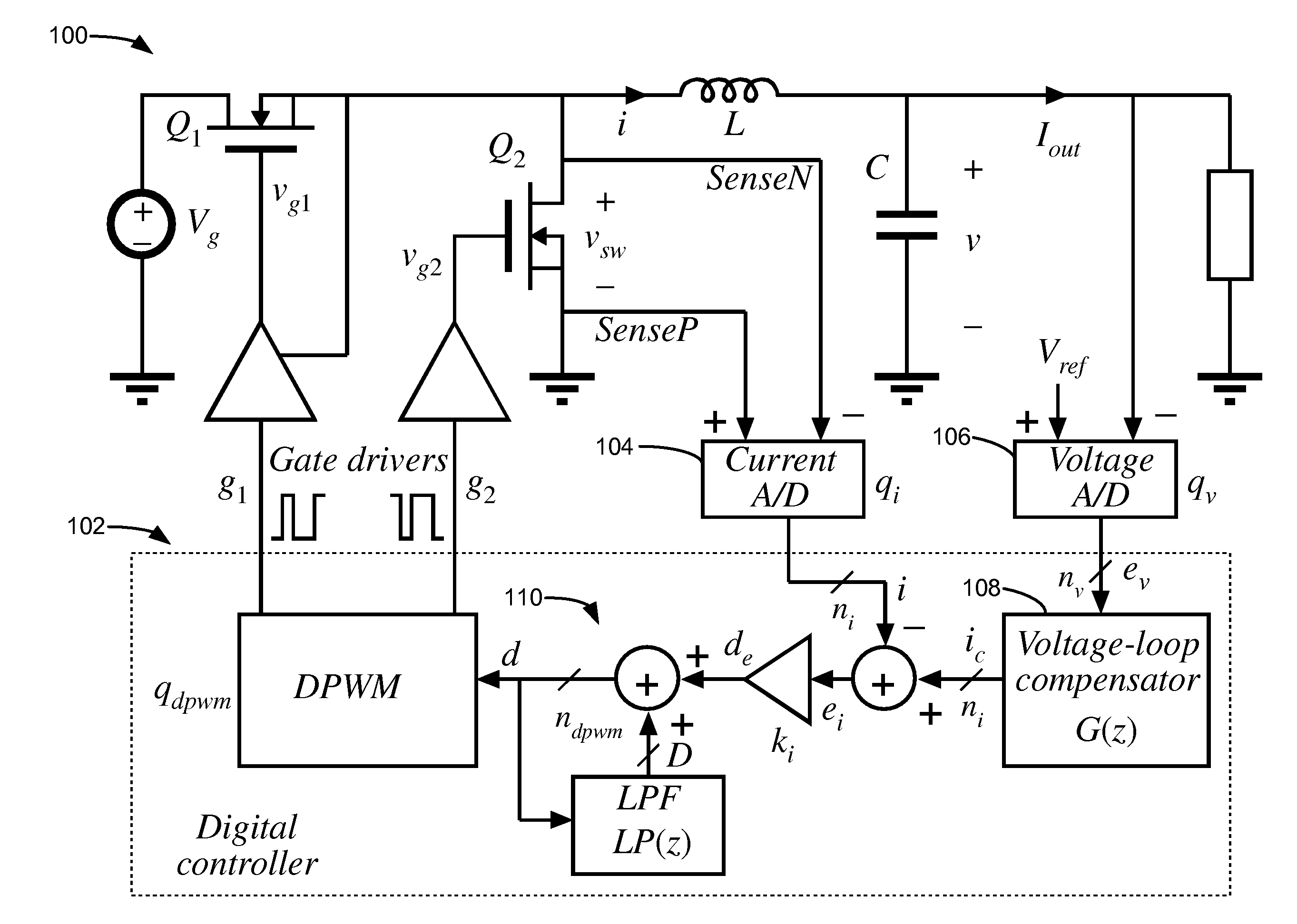
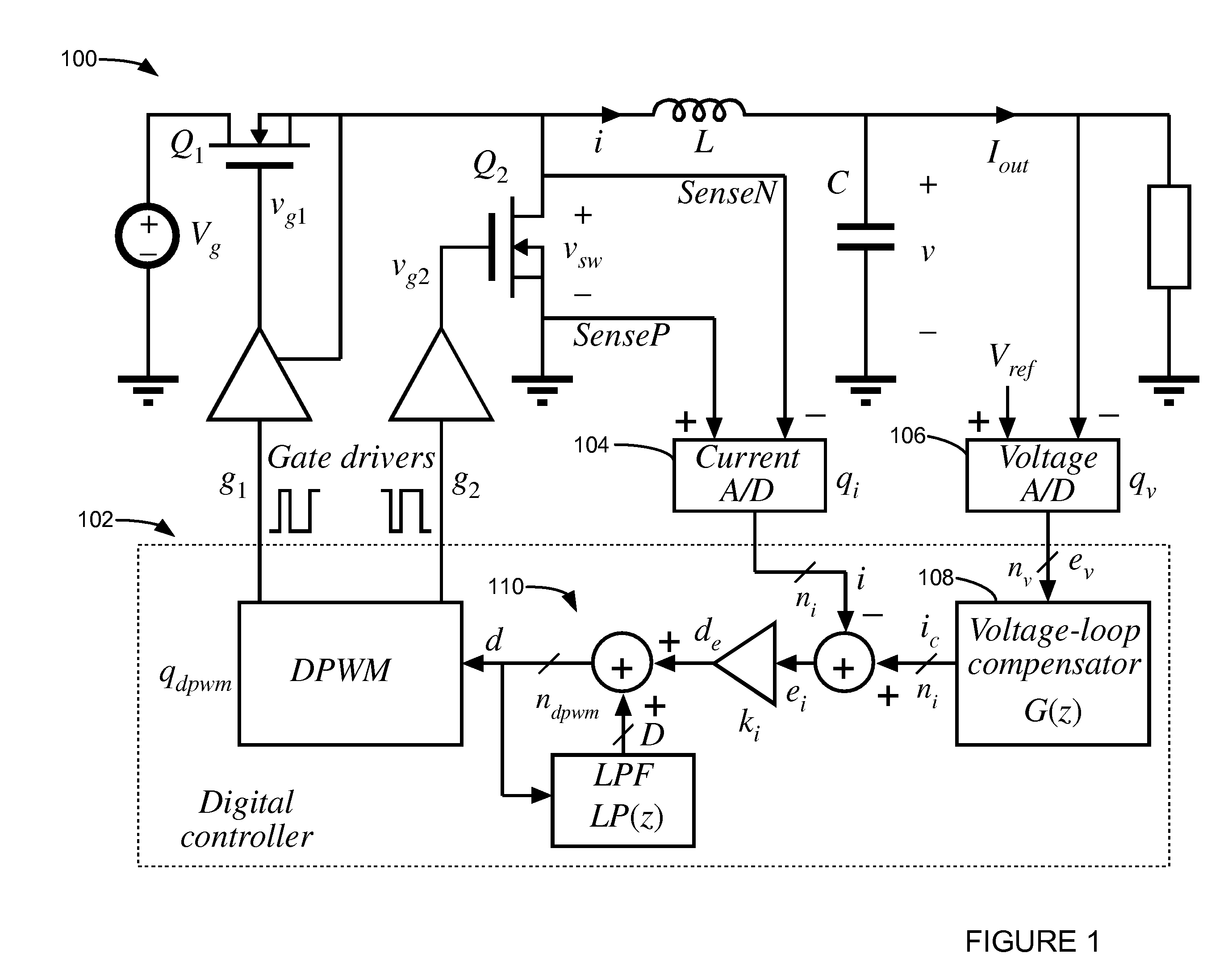
[0025]A solution that has the potentials of combining advantages of digital control and current-mode controller in a relatively simple controller realization based on a low-resolution current A / D converter is provided. One implementation of a controller architecture is shown in FIG. 1. FIG. 1 shows a switched-mode DC-DC converter 100, a controller 102, a current A / D converter 104, and a voltage A / D converter 106.

[0026]The architecture comprises a two-loop approach. The output voltage is sensed and compared to a voltage reference to determine an error signal ev via the voltage A / D converter 106. The error signal is converted to a digital voltage reference signal ei. A voltage-loop compensator 108 computes a digital current reference signal ic. A digital representation of the inductor current i is obtained by sensing the voltage across a synchronous rectifier Q2 using the current A / D converter 106. The architect...


PUM

PropertyMeasurementUnit
Currentaaaaaaaaaa
Electric potential / voltageaaaaaaaaaa
Widthaaaaaaaaaa

Abstract

A digital current-mode controller for a DC-DC converter is disclosed. The controller comprises a digital current reference; and a current loop compensator adapted to receive a digital current error signal derived from a digital current sample sensed from the DC-DC converter and the digital current reference and to generate a duty-cycle command, wherein the current loop compensator comprises a low-pass filter that is used in generating the duty-cycle command. A DC-DC regulator comprising a digital current-mode controller and a method of controlling a DC-DC converter are also disclosed.

Description

CROSS-REFERENCE TO RELATED APPLICATIONS[0001]This application claims the benefit of U.S. provisional application No. 60 / 658,768, filed 4 Mar. 2005, which is hereby incorporated by reference as though fully set forth herein.[0002]This application is a continuation-in-part of U.S. application Ser. No. 11 / 369,888, filed 6 Mar. 2006, now pending (the '888 application), which also claims the benefit of and incorporates in its entirety by reference U.S. provisional application No. 60 / 658,768, filed 4 Mar. 2005 (the '768 application). The '888 application and the '768 application are both hereby incorporated by reference in their entirety including any material incorporated by reference therein as though fully set forth herein.BACKGROUND[0003]a. Field of the Invention[0004]The instant invention relates to digital current mode controllers. In particular, the instant invention relates to digital current mode controllers for DC-DC converters.[0005]b. Background Art[0006]Practical high-frequen...

Claims


Application Information

Patent Timeline
IPC IPC(8): H02J1/00
CPCH01L27/0266H02M3/157H03K17/0822H03M1/502H03M1/1042H03M1/1295H03K17/6871
Inventor PENG, HAOMAKSIMOVIC, DRAGAN
Owner UNIV OF COLORADO THE REGENTS OF
Learn More