Projection optical apparatus, exposure method and apparatus, photomask, and device and photomask manufacturing method

a technology of projection optical apparatus and exposure method, applied in the direction of photomechanical treatment, printing, instruments, etc., can solve the problems of further increase and higher cost, and achieve the effect of reducing image oscillation, optimum pattern transfer, and well-balanced manner

Active Publication Date: 2008-07-10
NIKON CORP
View PDF6 Cites 23 Cited by
  • Summary
  • Abstract
  • Description
  • Claims
  • Application Information

AI Technical Summary

Benefits of technology

[0018]The projection optical apparatus and the first projection optical apparatus of the above aspect, using, for example, light beam transfer members, transfers light beam from two view points or two rows of view points of two projection optical systems or two rows of projection optical systems so that the light beams are transferred on a second object in opposite directions along a first direction. The second projection exposure apparatus of the above aspect includes two projection optical systems, each forming a magnified inverted image in a scanning direction, and transfers light beam from two view points of the two projection optical systems so that the light beams are transferred on a second object in opposite directions along the scanning direction. As a result, images formed in pattern fields on the first object are projected by the two projection optical systems or by the two-rows of projection optical systems and are formed on the second object in a manner that the images are continuous to one another. This enables optimum pattern transfer.
[0019]The amount of light beam transferred by a first light beam transfer member and the amount of light beam transferred by a second light beam transfer member at least overlap each other as viewed in a second direction. The amount of light beam transferred from a view point to an image point by the first-row projection optical system and the amount of light beam transferred from a view point to an image point by the second-row projection optical system overlap with each other as viewed in the second direction. This means that the first and second projection optical systems are in a nested arrangement and the first-row and second-row projection optical systems are in a nested arrangement. This arrangement enables miniaturization of the entire projection optical apparatus, and reduces image oscillation, which may occur when the apparatus is subjected to disturbance such as vibration.
[0020]The offset of the position of each pattern field on the first object in the first direction (scanning direction), which is subjected to projection performed by the two projection optical systems or the two rows of projection optical systems, and the scanning distance of the second object during scanning exposure are optimized in a well-balanced manner by adjusting the overlap amount etc. of the light beam transfer amount etc. The offset may be set to zero as necessary. In this case, the base member of the stage of the first object may be reduced in size. As a result, the pattern is formed with a higher precision. When the scanning distance is shortened, the base member of the stage of the second object may be reduced in size. Further, the exposure time is shortened and the exposure throughput is improved.

Problems solved by technology

A larger mask results in higher costs due to the need to maintain flatness of the mask substrate and the more complicated manufacturing process that becomes necessary when the mask is enlarged.
This further increases costs.

Method used


Image

  • Projection optical apparatus, exposure method and apparatus, photomask, and device and photomask manufacturing method
  • Projection optical apparatus, exposure method and apparatus, photomask, and device and photomask manufacturing method
  • Projection optical apparatus, exposure method and apparatus, photomask, and device and photomask manufacturing method

Examples


first embodiment

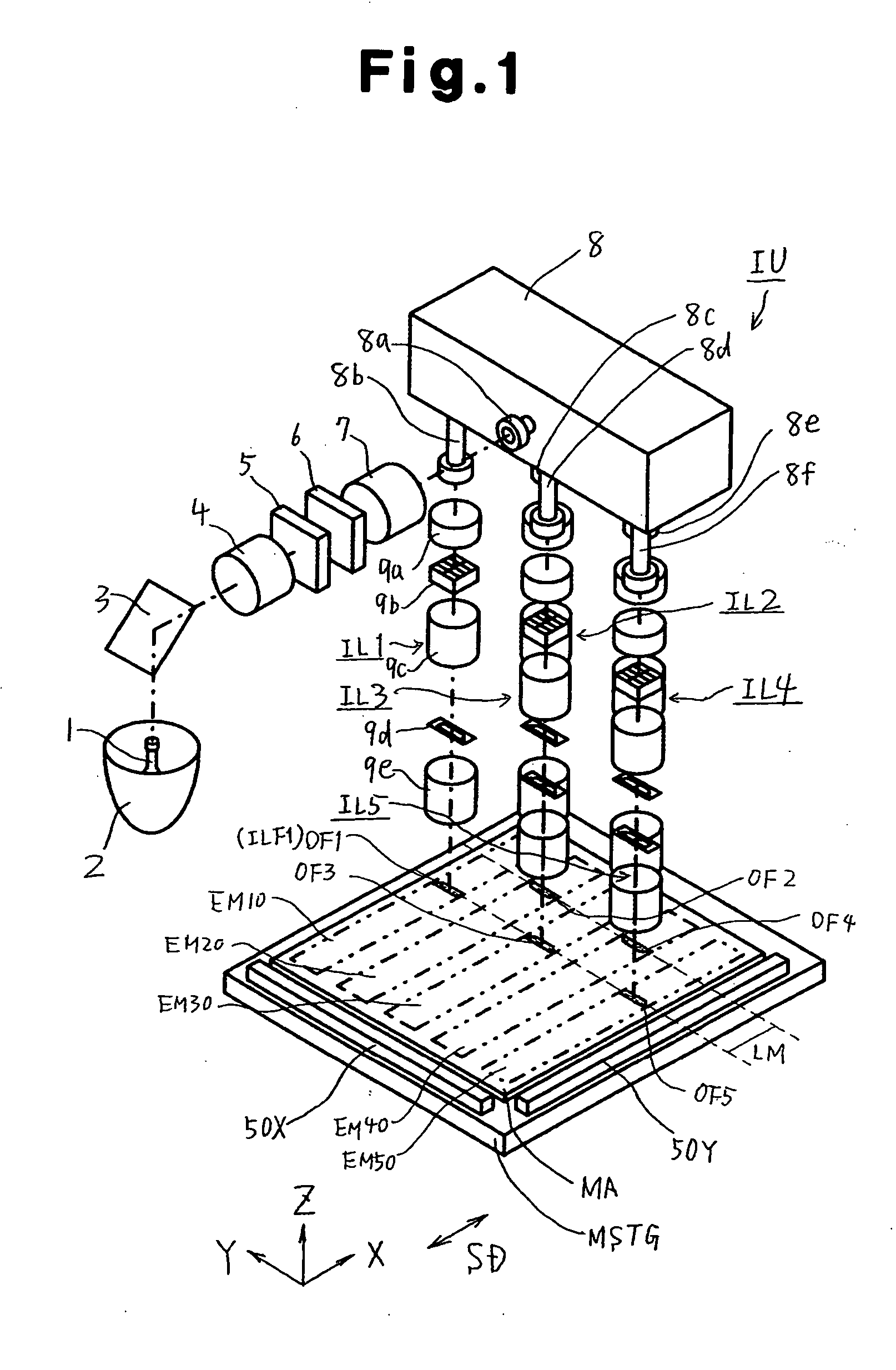
[0047]A first embodiment of the present invention will now be described with reference to FIGS. 1 to 12.

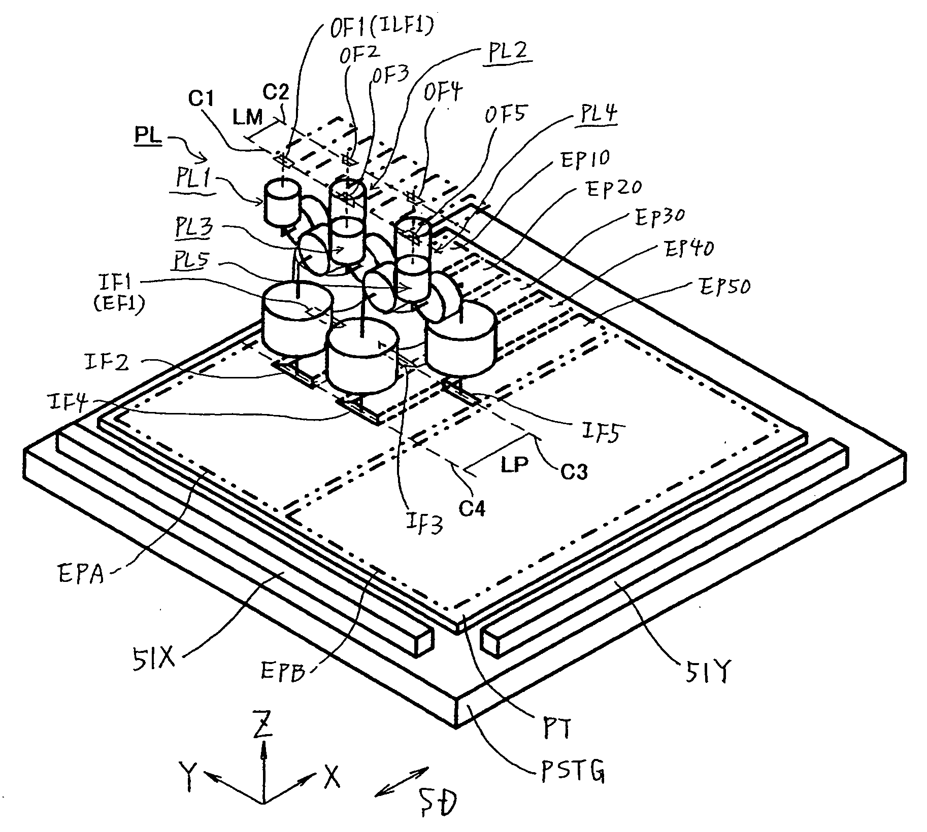
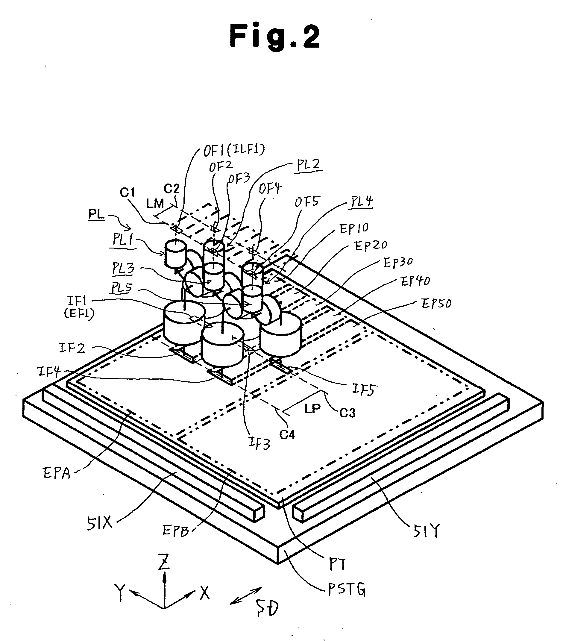
[0048]FIG. 1 shows a schematic structure of an illumination unit and a mask stage of a scanning projection exposure apparatus employing a step-and-scan method in the first embodiment. FIG. 2 shows a schematic structure of a projection optical apparatus and a substrate stage of the projection exposure apparatus. In FIGS. 1 and 2, the projection exposure apparatus includes an illumination unit IU, a mask stage MSTG, a projection optical system PL, a substrate stage PSTG, a drive mechanism (not shown), and a control unit (not shown). The illumination unit IU illuminates a pattern of a mask MA (first object) with illumination light emitted from a light source. The mask stage MSTG holds and moves the mask MA. The projection optical system PL projects a magnified image (an image with an enlargement magnification) of the pattern of the mask MA onto a plate (substrate) PT (second object)....

second embodiment

[0102]A second embodiment of the present invention will now be described with reference to FIGS. 14 to 20. A stage system of a scanning projection exposure apparatus according to the second embodiment is similar to the stage system described in the first embodiment. However, a projection exposure apparatus of the second embodiment differs from the projection optical apparatus PL of the first embodiment shown in FIG. 2 in the shift direction and the shift amount of light beams (optical axes) of each of its projection optical systems PL1 to PL5. The components shown in FIGS. 14 to 20 corresponding to the components shown in FIGS. 1 to 5 are given the same reference numerals and will not be described in detail.

[0103]FIGS. 14(A) to 14(C) show a projection optical apparatus PLA of the second embodiment. FIG. 14(A) is a plan view showing the arrangement of a plurality of pattern fields EM10 to EM50 formed on a mask MA. FIG. 14(B) is a projection view showing the arrangement of the plurali...

third embodiment

[0133]A third embodiment of the present invention will now be described with reference to FIGS. 21 to 24. In the third embodiment, a manufacturing method for a mask on which patterns are transferred using the projection optical apparatus PL of each of the above embodiments (e.g., the mask MA in FIG. 1) will be described.

[0134]FIG. 21 is a conceptual diagram describing the positional relationship between patterns of the mask and the patterns transferred onto the plate in the embodiment shown in FIGS. 1 and 2. In FIG. 21, a mask MA1 includes a pattern field EM10 in a first row and a pattern field EM20 in a second row, which are spaced from each other in a non-scanning direction (Y-direction). The pattern fields EM10 and EM20 have a length in the longitudinal direction that coincides with a scanning direction (X-direction).

[0135]The first-row pattern field EM10 includes a first pattern field RP10, of which has a length in the longitudinal direction coinciding with the scanning directio...


PUM

PropertyMeasurementUnit
sizeaaaaaaaaaa
wavelengthaaaaaaaaaa

Abstract

When forming a magnified image of a mask pattern on an object with a plurality of projection optical systems, projected images of the projection optical systems are formed to be accurately continuous to enable satisfactory pattern transfer. A first projection optical system directs light beam from point a on a mask to point A on a plate and forms a magnified image of the mask on the plate. A second projection optical system directs light beam from point b on the mask to point on the plate and forms a magnified image of the mask on the plate. A first line segment linking point A and point a′, which orthogonally projects point a on the plate, and a second line segment linking point B and point b′, which orthogonally projects point b on the plate PT, overlap each other as viewed in a non-scanning direction.

Description

CROSS-REFERENCE TO RELATED APPLICATIONS[0001]This application is based upon and claims the benefit of priorities from U.S. Provisional Application No. 60 / 878,383 filed on Jan. 4, 2007, the entire contents of which are incorporated herein by reference.BACKGROUND OF THE INVENTION[0002]The present invention relates to a projection optical apparatus for forming a magnified image of a first object such as a mask onto a second object such as a photosensitive substrate, and to an exposure technique and a device manufacturing technique using such a projection optical apparatus. The present invention further relates to a photomask on which a pattern transferred by the projection optical apparatus is formed and to a method for manufacturing such a photomask.[0003]A projection exposure apparatus, which projects a pattern of a mask (e.g., reticle or photomask) onto a resist-coated plate (e.g., glass plate or semiconductor wafer) using a projection optical system, is used when manufacturing devi...

Claims


Application Information

Patent Timeline
Patent Type & Authority Applications(United States)
IPC IPC(8): G03B27/42G03B27/54G03F1/00
CPCG03F7/70216G03F7/70791G03F7/70475G03F7/70275G03F7/7015G03F7/70258
Inventor KUMAZAWA, MASATOHATADA, HITOSHI
Owner NIKON CORP
Why Eureka
Try Eureka