Optical Scanning Device and Method of Deriving Same

a scanning device and optical technology, applied in the field of optical scanning devices, can solve the problems of more complex and expensive, and achieve the effect of reducing the secondary maxima of the point-spread function and reducing the effect of saturation

Inactive Publication Date: 2008-07-10
DEUTES KREBSFORSCHUNGSZENT STIFTUNG DES OFFENTLICHEN RECHTS
View PDF7 Cites 15 Cited by
  • Summary
  • Abstract
  • Description
  • Claims
  • Application Information

AI Technical Summary

Benefits of technology

[0030]In another aspect of the present invention, the above mentioned optical scanning device is part of a multi-photon fluorescence microscope, in particular of the 4Pi type. The 4Pi type uses the 2-photon effect to reduce the secondary maxima of the point-spread

Problems solved by technology

But this is more co

Method used


Image

  • Optical Scanning Device and Method of Deriving Same
  • Optical Scanning Device and Method of Deriving Same
  • Optical Scanning Device and Method of Deriving Same

Examples


Embodiment Construction

[0046]The invention is now described with reference to several figures. It should be understood, however, that the invention is not limited to this description but is defined by the claims.

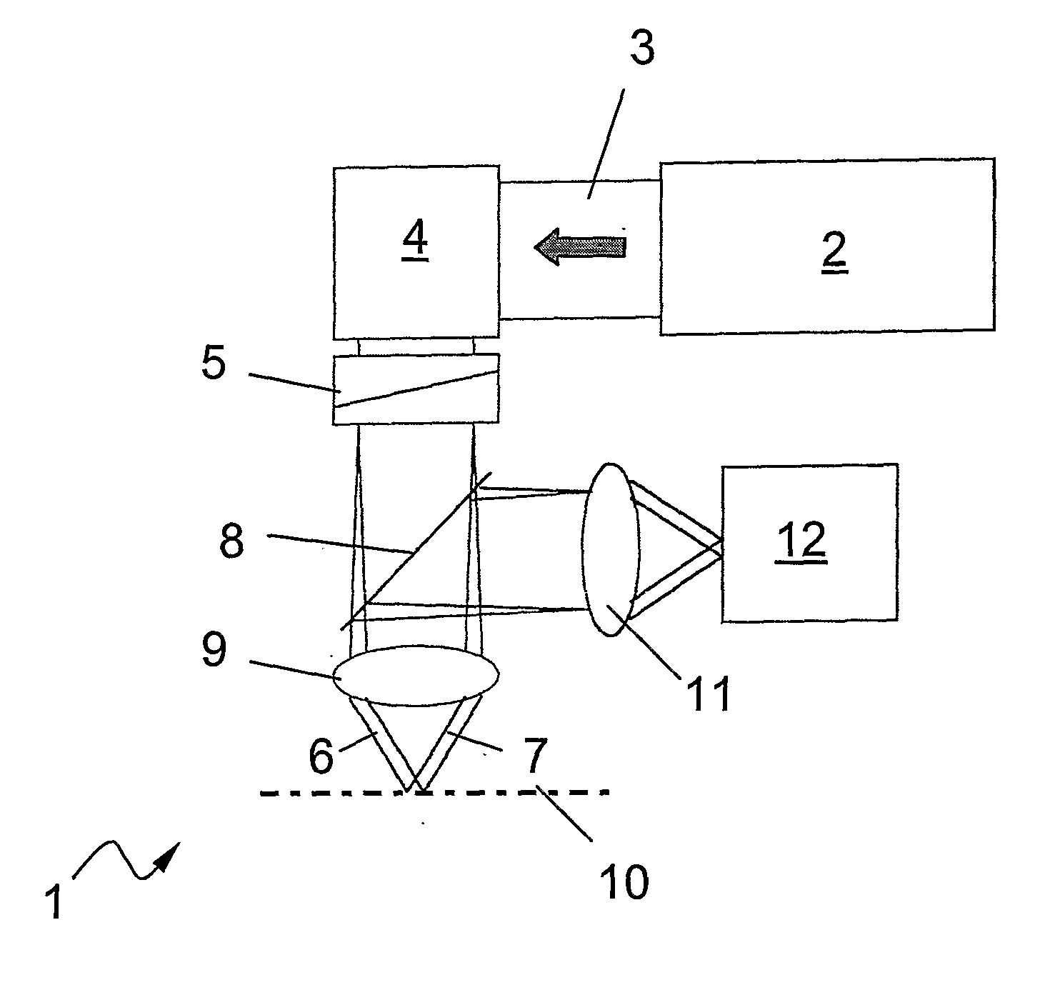
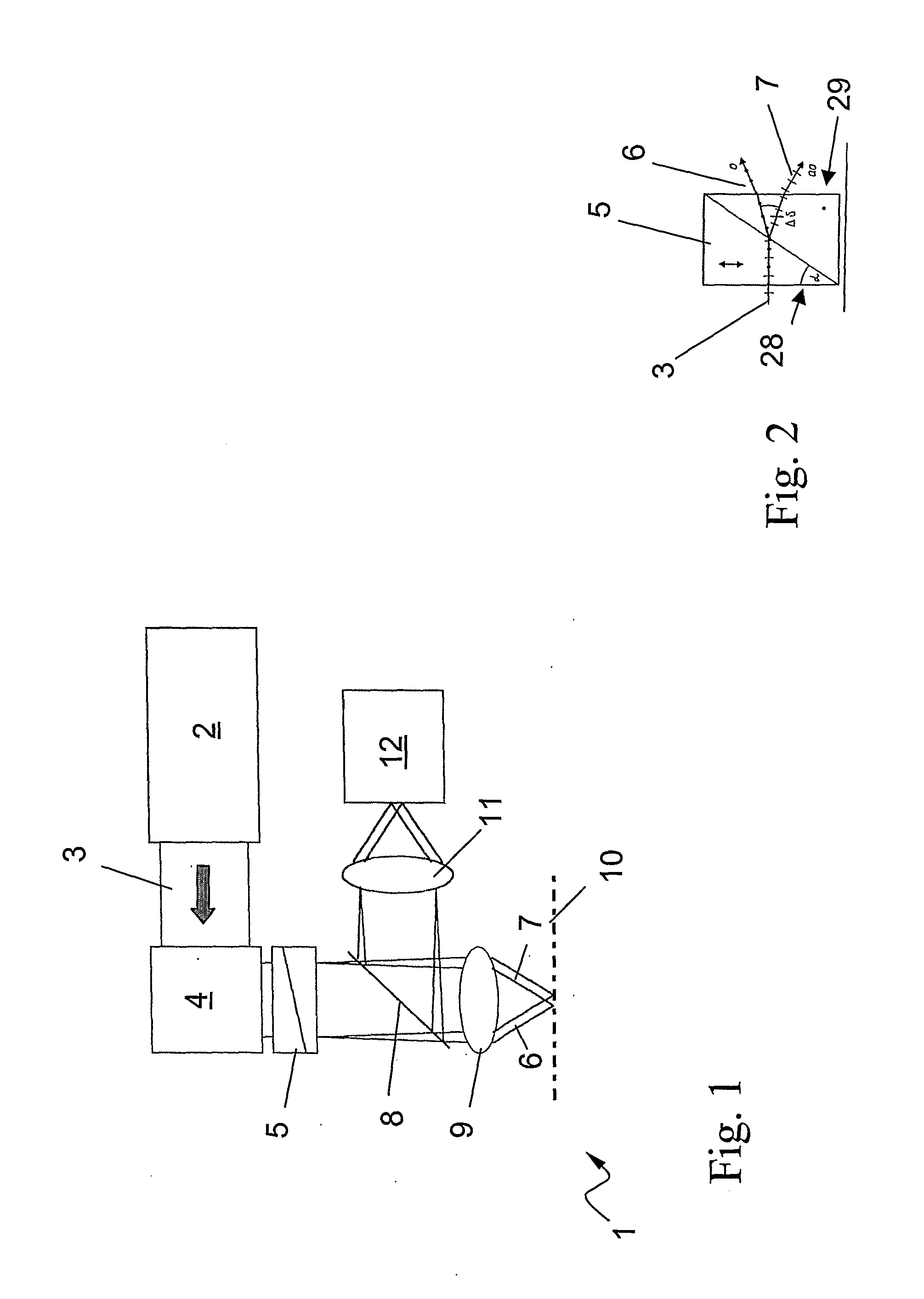
[0047]FIG. 1 is a simplified schematic diagram of a laser scanning device 1 using several beamlets.

[0048]The laser scanning device 1 comprises a laser 2 as a light source to emit a laser beam 3, as indicated by the arrow. the laser beam 3 enters a scanner 4 that moves the laser beam 3, e.g. in lines, to generate a scanning area. The laser beam 3 then enters a beam splitter 5 that splits the primary laser beam 3 into several, here: two, beamlets 6,7. The beamlets 6,7 then pass a dicroic mirror 8 that is at least semi-transparent for the Laser light. The beamlets 6,7 then pass a first objective lens 9 to direct the beamlets 6,7 onto a focal plane 10 wherein each of said beamlets 6,7 impinges on the focal plane 10 at locations separated from each other, i. e. without significant interference. The bea...


PUM


Abstract

The present invention relates to an optical scanning device that comprises a light source to emit a beam of light, and a beam splitter to split that beam into several beamlets, and further a first objective lens to direct said beamlets onto a focal plane wherein each of said beamlets impinges on the focal plane spacially separated from each other, wherein the beam splitter comprises several birefringent elements for splitting said beam, preferably a stack of Wollaston prisms.

Description

BACKGROUND OF THE INVENTION[0001]1. Field of the Invention[0002]The present invention relates generally to optical scanning devices, and more particularly, to multi-photon fluorescence microscopes.[0003]2. Related Art[0004]Optical scanning devices, e.g. laser scanning microscopes are used to scan samples multi-dimensionally by directing a beam of light over the sample's surface to obtain a multi- (two- or three-) dimensional view.[0005]If fast effects, e.g. structural re-arrangements or chemical reactions, are to be measured, the scanning must be correspondingly fast. A faster scanning can be achieved by moving the beam faster across the surface.[0006]In most cases one cannot compensate for that by simply increasing the illumination intensity since this increasingly leads to saturation of the fluorescence dye, to stronger bleaching or even worse to damaging processes in the sample. This is also true for multi-photon fluorescence microscopes. Here the fluorescent molecules, e.g. GFP,...

Claims


Application Information

Patent Timeline
IPC IPC(8): G02B27/28G01J4/00
CPCG02B21/0076G02B21/0036
Inventor ENGELHARDT, JOHANN
Owner DEUTES KREBSFORSCHUNGSZENT STIFTUNG DES OFFENTLICHEN RECHTS
Why Eureka
Try Eureka