Ultrasonic diagnostic equipment and method for processing signal of ultrasonic diagnostic equipment

a diagnostic equipment and ultrasonic technology, applied in tomography, instruments, using reradiation, etc., can solve the problems of inability to confirm the target, the tumor image is hidden and invisible, and the deviation cannot be corrected

Inactive Publication Date: 2008-07-10
OLYMPUS MEDICAL SYST CORP
View PDF4 Cites 17 Cited by
  • Summary
  • Abstract
  • Description
  • Claims
  • Application Information

AI Technical Summary

Problems solved by technology

Therefore, when a tumor image is displayed in the B mode image display region on a display surface of an image display device and when a blood flow display region is moved to a part where the tumor image is present to display the blood flow of the portion, if the blood flow display region lies on the tumor image while the blood flow display region is moving, the tumor image is hidden and becomes invisible, and the target cannot be confirmed.
Therefore, the tumor image always has to be kept to be displayed on the display surface by correcting the deviation of the orientation of the echo sounder transducer while watching the screen, but if the target becomes invisible partway as described above, the deviation cannot be corrected if the orientation of the echo sounder transducer deviates.

Method used


Image

  • Ultrasonic diagnostic equipment and method for processing signal of ultrasonic diagnostic equipment
  • Ultrasonic diagnostic equipment and method for processing signal of ultrasonic diagnostic equipment
  • Ultrasonic diagnostic equipment and method for processing signal of ultrasonic diagnostic equipment

Examples


embodiment 1

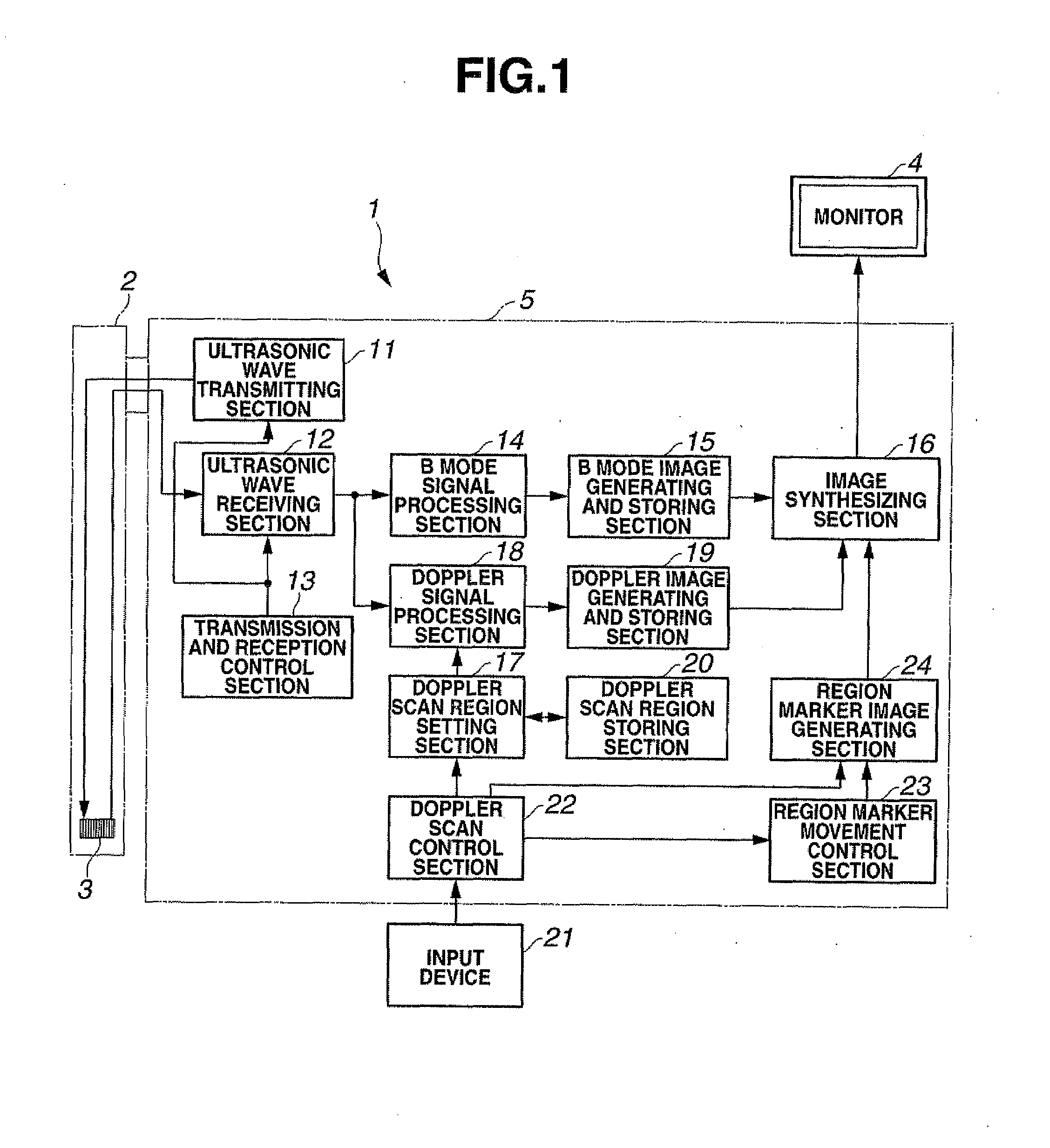
[0066]As shown in FIG. 1, ultrasonic diagnostic equipment 1 of the present embodiment is configured by including an ultrasonic probe 2 which is inserted into a luminal organ in a body cavity, and has, at a distal end portion, an ultrasonic transducer unit 3 transmitting and receiving ultrasonic waves to and from a part of interest such as an affected part in the luminal organ, and an image processing device 5 which ultrasonically drives the ultrasonic transducer unit 3 and displays an ultrasonic image on a monitor 4 by an ultrasonic echo signal.

[0067]The image processing device 5 is configured by including an ultrasonic wave transmitting section 11, an ultrasonic wave receiving section 12, a transmission and reception control section 13, a B mode signal processing section 14, a B mode image generating and storing section 15, an image synthesizing section 16, a Doppler signal processing section 18, a Doppler image generating and storing section 19, a Doppler scan region setting secti...

embodiment 2

[0097]Embodiment 2 is substantially the same as the embodiment 1. Therefore, only the point differing from the embodiment 1 will be described, and the explanation of the same components will be omitted by assigning the same reference numerals and characters to them.

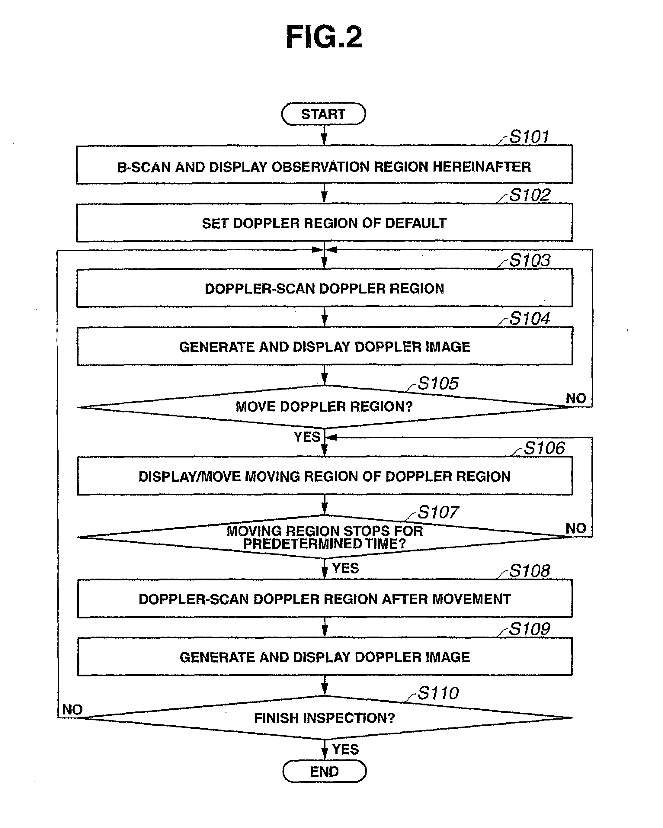
[0098]An operation of the present embodiment will be described by using flowcharts in FIGS. 8 and 17, and explanatory diagrams in FIGS. 3 and 9 to 16.

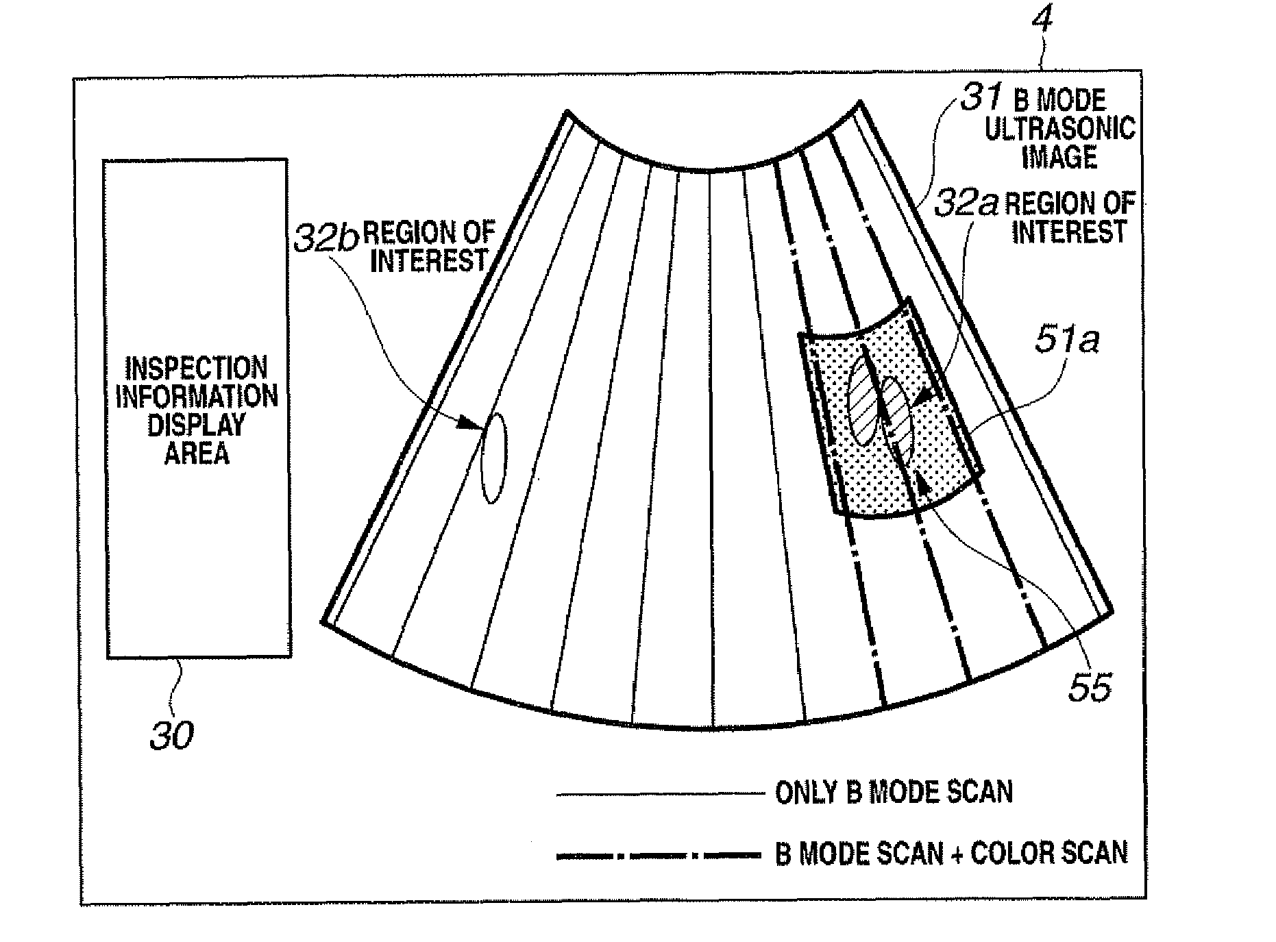
[0099]When an operator inserts the ultrasonic probe 2 into a luminal organ in a body cavity and starts diagnosis, the ultrasonic diagnostic equipment 1 of the present embodiment performs B mode scan for an observation region of the luminal organ, and displays the B mode ultrasonic image 31 on the monitor 4 as in the embodiment 1 in step S1 as shown in FIG. 8 (see FIG. 3). The monitor 4 on which the B mode ultrasonic image 31 is displayed displays the inspection information area 30 for displaying inspection information (patient information, inspection date and time and the li...

embodiment 3

[0123]Hereinafter, ultrasonic diagnostic equipment 100 according to a third embodiment of the present invention will be described with inclusion of comparison with the conventional ultrasonic diagnostic equipment. FIGS. 40 and 41 are both diagrams explaining monitor screens in the conventional ultrasonic diagnostic equipment. In the conventional ultrasonic diagnostic equipment, the number of blood flow display regions 51a (hereinafter, called a color display region) of which color image display (hereinafter, called color display) of the two-dimensional distribution of the blood flow can be made is only one in the region of the B mode image display 31. Therefore, in order to make color display of a plurality of target parts of interest 32a, 32b and 32c in the region of the B mode image display 31 in real time at the same time, there is no other method but to extend the color display region 51a including one part of interest 32a which is displayed in colors to be large as shown in FIG...


PUM


Abstract

In the present invention, an image processing device is configured by including an ultrasonic wave transmitting section, an ultrasonic wave receiving section, a transmission and reception control section, a B mode signal processing section, a B mode image generating and storing section, an image synthesizing section, a Doppler signal processing section, a Doppler image generating and storing section, a Doppler scan region setting section, a Doppler scan region storing section, a Doppler scan control section, a region marker movement control section and a region marker image generating section. By the configuration, an observation target of which blood state needs to be grasped can be always optimally observed in real time in a Doppler image by a Color Doppler mode or a Power Doppler mode.

Description

[0001]This application claims benefit of Japanese Applications No. 2007-000778 filed in Japan on Jan. 5, 2007 and Japanese Application No. 2007-223257 filed in Japan on Aug. 29, 2007, the contents of which are incorporated by this reference.BACKGROUND OF THE INVENTION[0002]1. Field of the Invention[0003]The present invention relates to ultrasonic diagnostic equipment and a method for processing a signal of ultrasonic diagnostic equipment which displays a blood flow image in a Color Doppler mode or a Power Doppler mode by ultrasonic waves in part of a B mode image display region.[0004]2. Description of the Related Art[0005]In recent years, in ultrasonic diagnostic equipment for medical use, ultrasonic waves are irradiated to a living body, and two-dimensional distribution of a blood flow is displayed in a color image by the power of a Doppler signal. Unlike the method for displaying a blood flow by the frequency of a Doppler signal, the direction and velocity of a blood flow, or velo...

Claims


Application Information

Patent Timeline
Patent Type & Authority Applications(United States)
IPC IPC(8): A61B8/14
CPCA61B8/06A61B8/13G01S15/8979G01S7/52063G01S7/52085A61B8/469
Inventor KOZAI, SHIGENORI
Owner OLYMPUS MEDICAL SYST CORP
Why Eureka
Try Eureka