

Molding machine and molding method
a molding machine and mold technology, applied in the field of molding machines and molding methods, can solve the problems of inconvenient use of such a conventional molding machine and the possibility of significant impact on one mold, and achieve the effect of less for
- Summary
- Abstract
- Description
- Claims
- Application Information
AI Technical Summary
Benefits of technology
Problems solved by technology
Method used
Image

Examples
Embodiment Construction
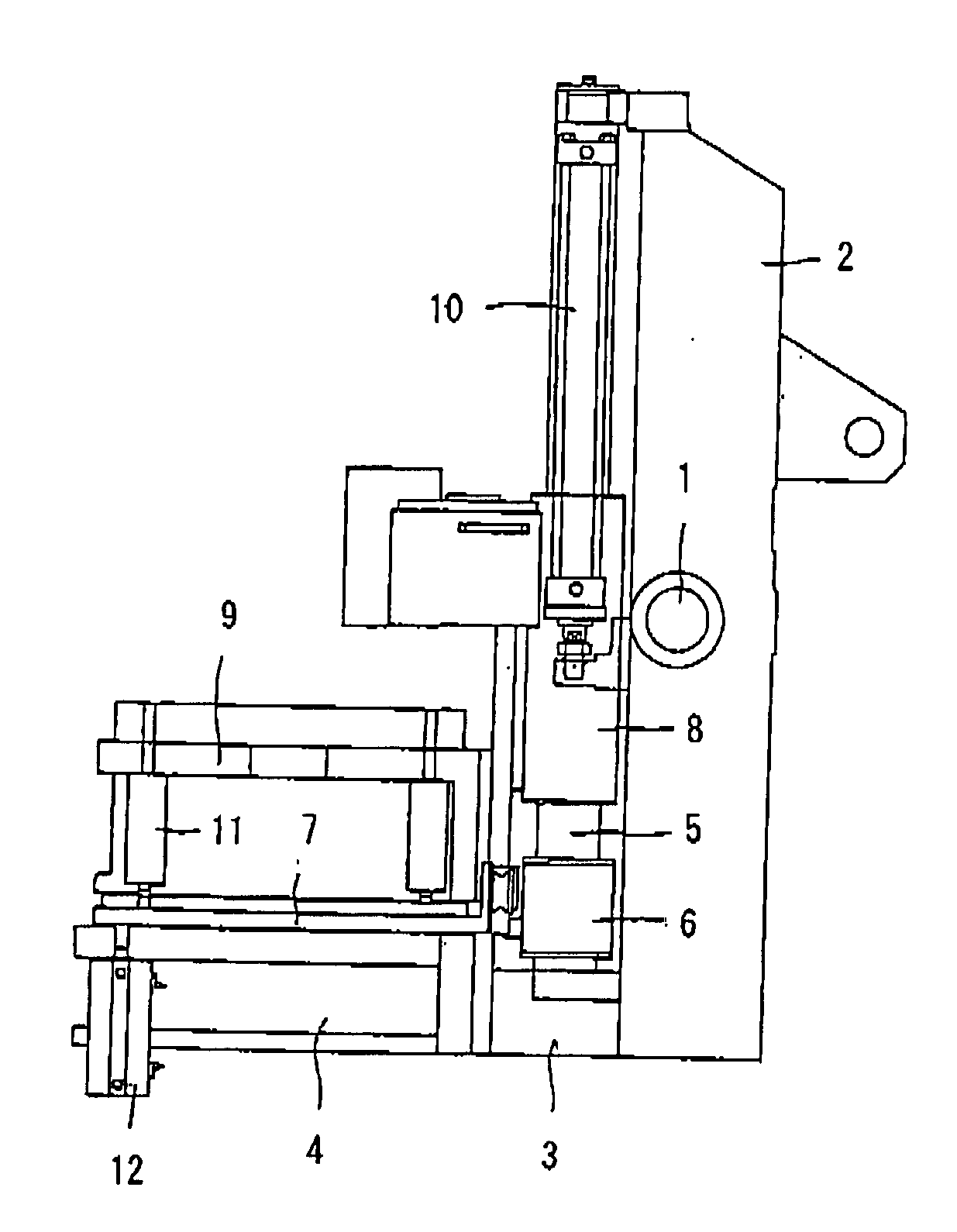
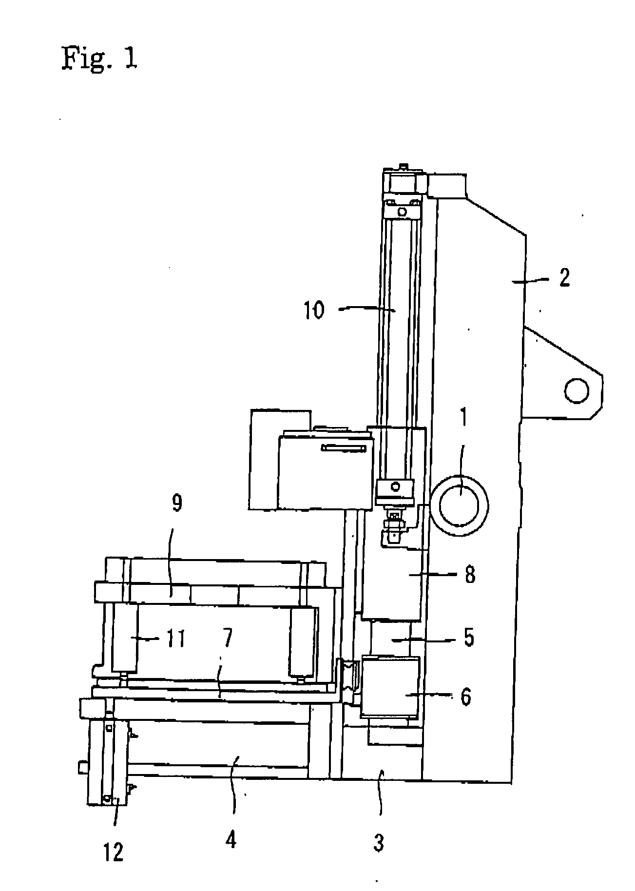
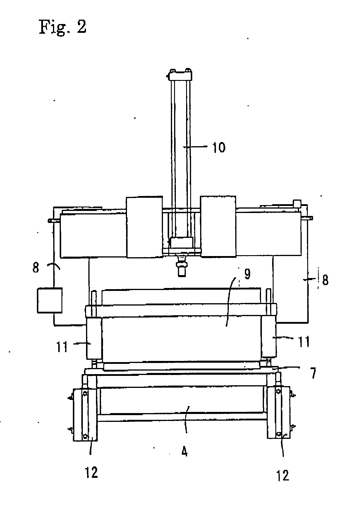
[0020]One embodiment of the match plate molding machine of the present invention will now be explained in detail by reference to FIGS. 1, 2, and 3. As shown in FIGS. 1 and 2, the molding machine of the present invention includes a rotating frame 2, which is extended substantially vertically. The rotating frame 2 is pivotally mounted on a supporting shaft 1 such that it can be moved up and down in the vertical plane about the supporting shaft 1. A drag flask 4, whose sidewall has sand-filling ports, is mounted on the lower end of the rotating frame 2 via a supporting member 3. On the left side of the rotating frame 2, a pair of guide rods 5 is attached at a predetermined interval therebetween in back and front such that they extend substantially vertically. On the guide rods 5, a match plate 7 is slidably and vertically mounted via guide holders 6. Immediately above the guide holders 6 of the guide rods 5, a cope flask, whose sidewall has sand-filling ports, is slidably and verticall...
PUM
| Property | Measurement | Unit |
|---|---|---|
| molding space | aaaaa | aaaaa |
| molding spaces | aaaaa | aaaaa |
| molding | aaaaa | aaaaa |
Abstract
Description
Claims
Application Information