Rotor for hybrid step motor with smooth motion

Inactive Publication Date: 2008-07-17
LIN TED T +1
View PDF8 Cites 9 Cited by
  • Summary
  • Abstract
  • Description
  • Claims
  • Application Information

AI Technical Summary

Benefits of technology

[0008]The present invention is a hybrid step motor in which two groups of rotor sections are displaced from one another by an amount selected to create extra detent positions within the fundamental full step positions. In particular, the displacement is specified as one-half rotor tooth pitch plus-or-minus one-quarter of the motor's fundamental step angle. This particular displacement minimized the rotor and stator teeth lineup at any one motor position, multiplying the number of detent positions and allowing the rotor to pass through the natural detent positions more smoothly and less erratically. As a result, micro-step accuracy is greatly improved.
[0009]The changes provided to the rotor can

Problems solved by technology

Due to the stable nature of a detent position, where rotor and stator teeth are in maximum alignment, the rotor has difficulty pulling out of the detent position.
When microstepping, this problem may manifest as erra

Method used


Image

  • Rotor for hybrid step motor with smooth motion
  • Rotor for hybrid step motor with smooth motion
  • Rotor for hybrid step motor with smooth motion

Examples


examples

Number of Rotor Teeth T=50 (Rotor Tooth Pitch=7.2°):

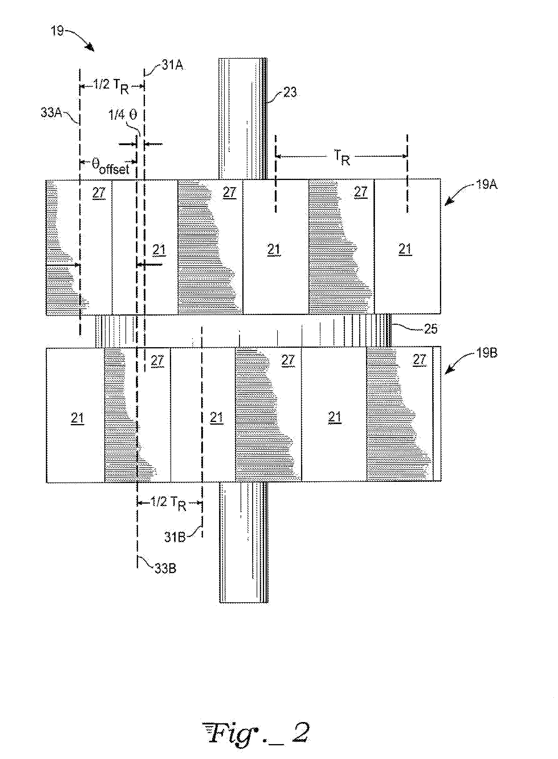
[0021]For a two-phase bipolar (four-phase unipolar) motor (P=2), the fundamental full-step angle is 1.8°. The offset angle θoffset=3.6°±0.45°=3.15° or 4.05°.

[0022]For a three-phase bipolar (six-phase unipolar) motor (P=3), the fundamental full-step angle is 1.2°. The offset angle θoffset=3.6°±0.30°=3.30° or 3.9°.

[0023]For a five-phase bipolar (ten-phase unipolar) motor (P=5), the fundamental full-step angle is 0.72°. The offset angle θoffset=3.6°±0.18°=3.42° or 3.78°.

[0024]Note that the corresponding mechanical displacement angles αm for suppressing torque harmonics, as taught by Brigham in U.S. Pat. No. 4,739,201, are 3.6° for suppressing the fundamental (h=1), 1.8° for suppressing the second harmonic (h=2), 1.2° for suppressing the third harmonic (h=3), etc. These values αm for suppressing harmonics differ substantially from either the displacement angle ¼·θ for offset angle θoffset for the rotor sections of the present invention...


PUM


Abstract

A hybrid step motor creates additional detent positions between successive drive phases of the motor for smooth motion and micro-step accuracy. A multi-section rotor has two sets of rotor sections that are displaced by the standard one-half rotor tooth pitch plus-or-minus an additional displacement angle equal to one-quarter of the fundamental step angle. The motor can also employ a stator in which two groups of teeth on the stator poles are displaced from the standard stator tooth pitch by an amount selected to create even more detent positions.

Description

TECHNICAL FIELD[0001]The invention related generally to electric motor structures designed to rotate step by step, i.e., the rotor is specially adapted for smooth motion and accurate microstepping.BACKGROUND ART[0002]Step motors are used in a wide variety of applications that require precise motion control, such as printers, scanners, x-y tables, turntables, tape and disk drive systems, security cameras and other optical equipment, robotics, CNC (computer-numeric-control) machines tools, dispensers, and injector pumps. A wide variety of step motor designs have been introduced in order to achieve specific performance goals, such as reduced noise and vibration, increased resolution and accuracy of motor positions, adequate holding torque, and efficient power usage over a range of motor speeds. These different performance factors are net in a variety of ways to be the step motor designs, often involving tradeoffs or compromises.[0003]A step motor is characterized by stable detent posit...

Claims


Application Information

Patent Timeline
IPC IPC(8): H02K37/14H02K37/12
CPCH02K37/18
Inventor LIN, TED T.LIN, RYAN C.
Owner LIN TED T
Why Eureka
Try Eureka