Image processor, driving assistance system, and out-of-position detecting method

a technology of image processing and driving assistance, applied in the direction of image enhancement, television systems, instruments, etc., can solve the problems of insufficient driver generated image, inconvenient parameter values, and sometimes occurring differences in images, etc., to achieve accurate determination

Active Publication Date: 2008-07-17
SANYO ELECTRIC CO LTD
View PDF5 Cites 42 Cited by
  • Summary
  • Abstract
  • Description
  • Claims
  • Application Information

AI Technical Summary

Benefits of technology

[0014]An aspect of the invention provides an image processor capable of accurately determining whether a vehicle camera has moved out of its proper position, the image processor generating a synthesis image by converting images imaged by a plurality of vehicle cameras into projection images projected on a plane while synthesizing the projection images.
[0017]That is, after confirming that there is no solid object in an image of the overlapping region, the difference between the image corresponding to the overlapping region within the first projection image, and the image corresponding to the overlapping region within the second projection image is calculated. Accordingly, it becomes possible to prevent the difference from being inaccurately calculated by the difference calculator due to an inclusion of a solid object within the image corresponding to the overlapping region, and to more accurately calculate the difference between the image corresponding to the overlapping region within the first projection image, and the image corresponding to the overlapping region within the second projection image.
[0018]In a driving assistance system which converts images imaged by a plurality of vehicle cameras into projection images projected on a plane, and which also generates a synthesis image by synthesizing the above-described projection images, it can be accurately determined whether vehicle cameras 10_1 to 10_4 have moved out of their proper positions.
[0021]That is, in the above-described image processor, it is determined whether there is a solid object by determining whether a plurality of motion vectors are uniform between an image of the overlapping region of the first projection image converted from a first image imaged at the first timing, and the first projection image converted from a first image imaged at the second timing. In this manner, in the above-described driving assistance system, it is determined whether there is a solid object or not, and when there is no solid object, the difference between the image corresponding to the overlapping region within the first projection image, and the image corresponding to the overlapping region within the second projection image is calculated. Consequently, the difference can be more accurately calculated.
[0025]As described above, the image processor determines whether there is a solid object in the overlapping region. When there is no solid object, the difference between the image corresponding to the overlapping region within the first projection image, and the image corresponding to the overlapping region within the second projection image is calculated. Consequently, it can be more accurately detected whether a vehicle camera has moved out of its proper position or not.
[0029]In this manner, in the above-described image processor, based on the number of times that the calculated difference consecutively reaches or exceeds the threshold value, it is determined and detected whether there is a solid object in the overlapping region, or whether a vehicle camera has moved out of its proper position. Consequently, it can be more accurately detected whether the vehicle camera has moved out of its proper position or not.

Problems solved by technology

In such cases, the parameter values become no longer suitable values, so that a generated synthesis image has parts of projection images synthesized out of their correct positions.
Consequently, the generated image is not adequate for the driver to check the peripheral situation.
However, in the aforementioned driving assistance system, even when a vehicle camera has not moved out of its proper position, a difference sometimes occurs in an image on an overlapping region of projection images.
In other words, when there is a solid object in overlapping region C, the above-described driving assistance system has a problem of failing to accurately detect whether a vehicle camera has moved out of its proper position, by use of the difference of the images corresponding to overlapping region C.

Method used


Image

  • Image processor, driving assistance system, and out-of-position detecting method
  • Image processor, driving assistance system, and out-of-position detecting method
  • Image processor, driving assistance system, and out-of-position detecting method

Examples


first embodiment

(Operation / Effect of Driving Assistance System of First Embodiment)

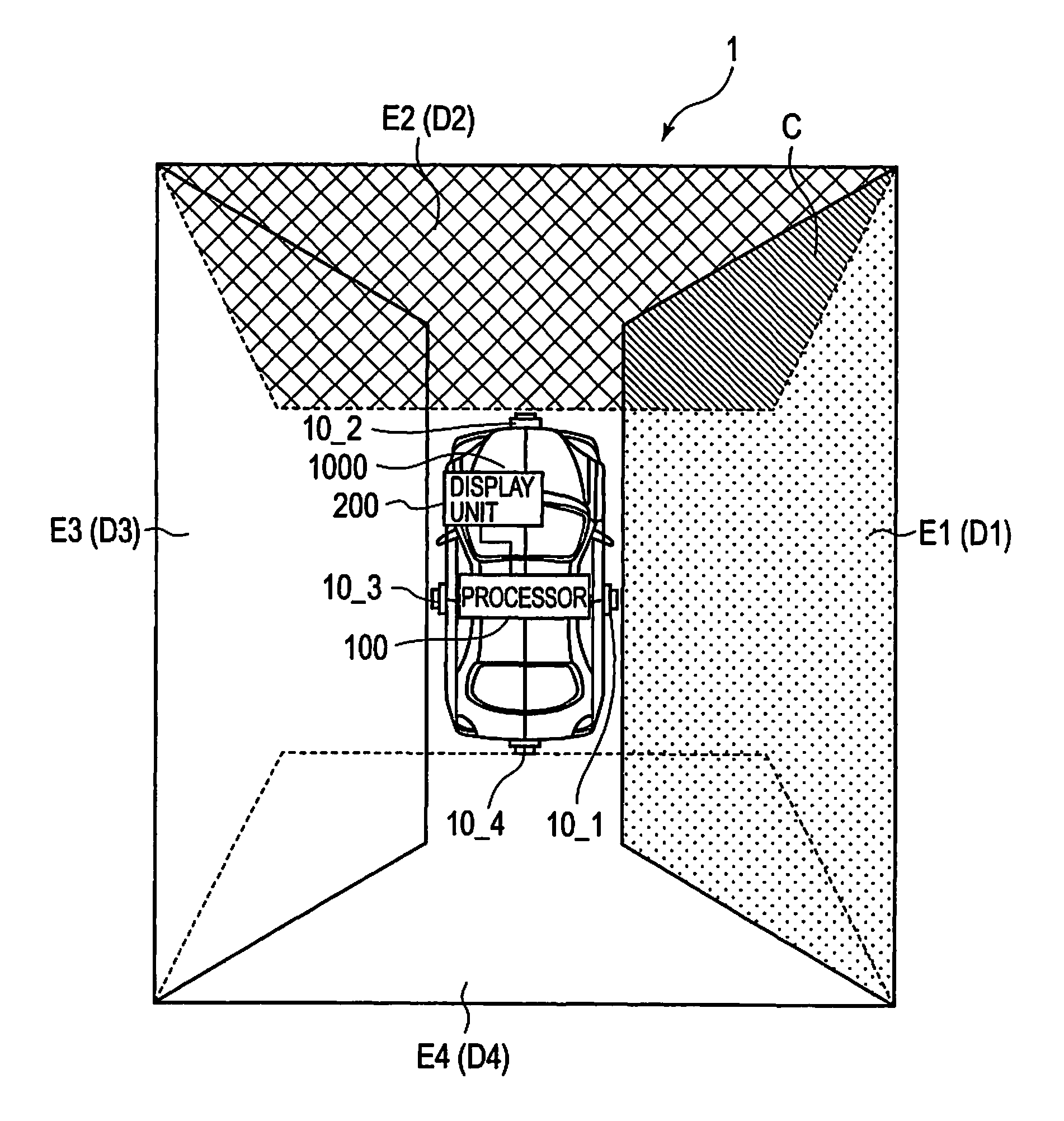
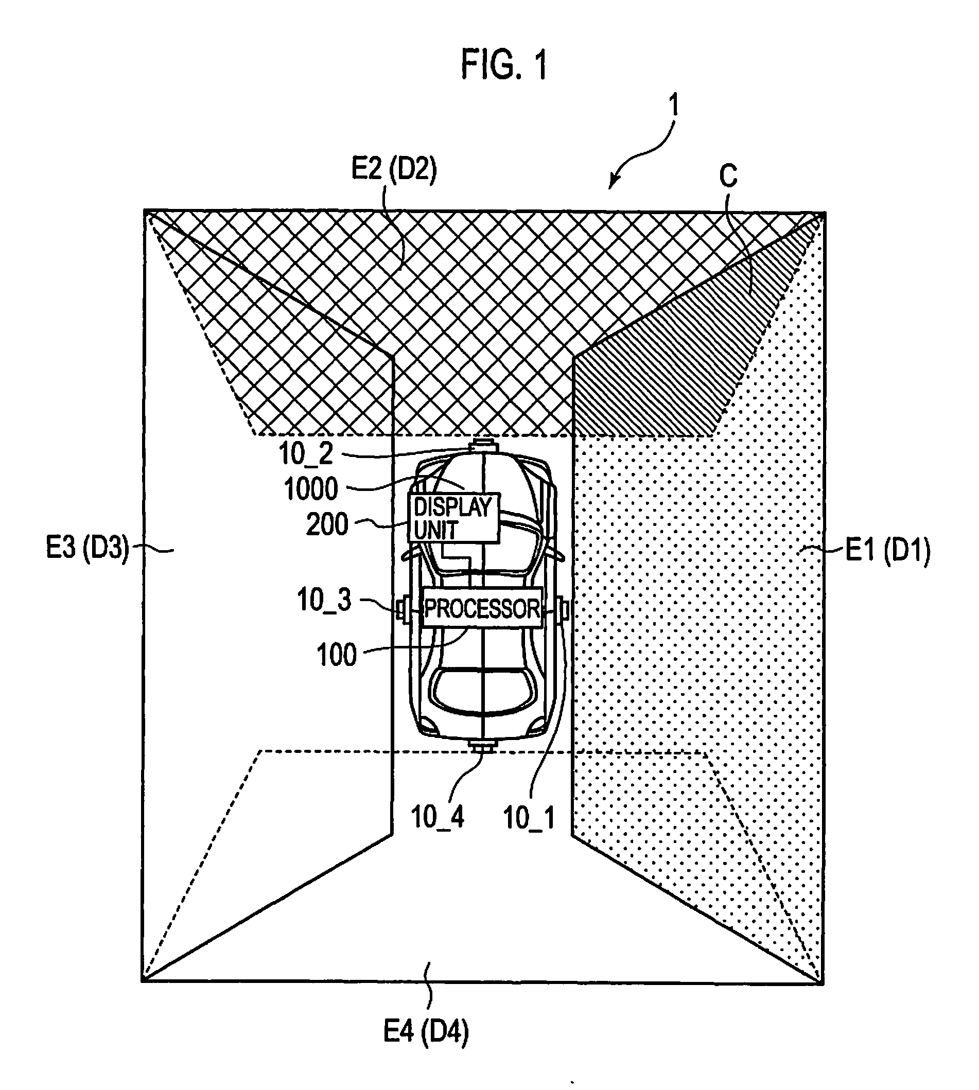
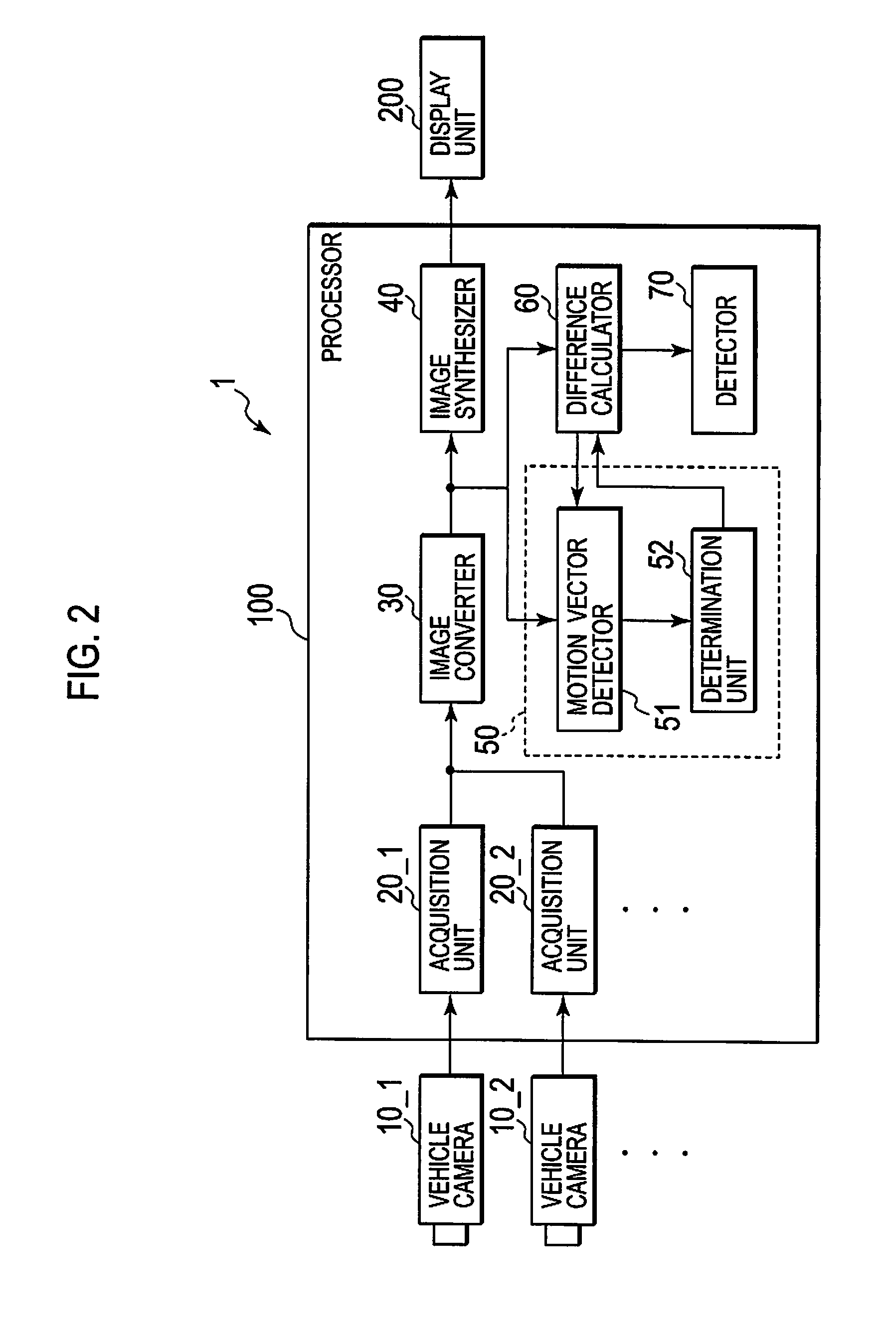
[0085]In driving assistance system 1 of the first embodiment, in processor 100, solid object determination unit 50 determines whether there is a solid object in an overlapping region within projection image E1, and when solid object determination unit 50 determines that there is no solid object, difference calculator 60 calculates a difference between an image corresponding to overlapping region C1 within projection image E1, and an image corresponding to overlapping region C2 within projection image E2.

[0086]That is, in processor 100, after confirming that there is no solid object in an image of overlapping region C, a difference between an image corresponding to overlapping region C1 within projection image E1, and an image corresponding to overlapping region C2 within projection image E2 is calculated. Therefore, driving assistance system 1 is capable of preventing the difference from being inaccurately calculated...

second embodiment

(Configuration of Driving Assistance System of Second Embodiment of Present Invention)

[0090]A second embodiment of the present invention will be described with particular attention focused on points different from the first embodiment. FIG. 7 is a block diagram showing processor 100 (an image processor) of this embodiment. As shown in FIG. 7, processor 100 further includes moving distance obtaining unit 80. Further, solid object determination unit 50 includes determination unit 53 and identifier 54.

[0091]While vehicle cameras 10_1 to 10_4 capture images periodically, moving distance obtaining unit 80 obtains a moving distance L of a vehicle between timing t1 (a first timing) and timing t2 (a second timing) coming after timing t1.

[0092]For example, moving distance obtaining unit 80 detects the number of rotations of a wheel in a period of timing t1 to timing t2. A moving distance L of a wheel is acquired based on the detected amount of rotations and an outer circumference stored in a...

third embodiment

(Configuration of Driving Assistance System of Third Embodiment of Present Invention)

[0106]A third embodiment of the present invention will be described with particular attention focused on points different from the first embodiment. FIG. 10 is a block diagram showing processor 100 (an image processor) of this embodiment. As shown in FIG. 10, processor 100 does not include solid object determination unit 50.

[0107]Further, difference calculator 60 of this embodiment calculates a difference between an image corresponding to overlapping region C1 within projection image E1, and an image corresponding to overlapping region C2 within projection image E2.

[0108]In addition, detector 70 of this embodiment detects that vehicle camera 10_1 or vehicle camera 10_2 has moved out of its proper position, based on the number of times that the difference calculated by difference calculator 60 consecutively takes a value not less than a threshold value.

[0109]To be more precise, detector 70 stores the...


PUM


Abstract

A driving assistance system that projects images imaged by multiple vehicle cameras onto a plane, and synthesizes projection images from images obtained at different times to accurately determine whether the vehicle cameras have moved out of their proper positions or imaging directions. The system includes: first and second in-vehicle cameras that capture first and second images, respectively. The cameras capture overlapping regions respectively in different directions. An image converter converts the first and second images into first and second projection images projected onto a plane. A solid object detection unit determines whether a solid object exists in the overlapping region. When no solid object exists, the images of the overlapping regions within the first and second projection images are compared to generate a comparison value. The comparison value is in turn compared with a threshold value for the determination of vehicle camera movement out of its proper position.

Description

CROSS REFERENCE TO RELATED APPLICATIONS[0001]This application claims priority based on 35 USC 119 from prior Japanese Patent Application No. P2007-003815 filed on Jan. 11, 2007, the entire contents of which are incorporated herein by reference.BACKGROUND OF THE INVENTION[0002]1. Field of the Invention[0003]The present invention relates to a driving assistance system, an image processor, and an out-of-position detection method in which: peripheral views of a vehicle are imaged by a plurality of vehicle cameras; and a plurality of images thus imaged are converted into projection images projected on a plane while the projection images projected on the plane are synthesized to generate a synthesis image.[0004]2. Description of Related Art[0005]Heretofore, driving assistance systems to allow a driver of a vehicle or the like to monitor a peripheral situation of the vehicle have been disclosed, for example, in Japanese Patent Application Laid-open Publication No. 2002-87160. In this drivi...

Claims


Application Information

Patent Timeline
Patent Type & Authority Applications(United States)
IPC IPC(8): H04N7/18
CPCB60W2050/0063B60W2050/0075B60W2420/403G06T2207/30252G06T7/0028G06T2207/10012B60W2420/42G06T7/33
Inventor HONGO, HITOSHIOKUDA, KOZO
Owner SANYO ELECTRIC CO LTD
Why Eureka
Try Eureka