Illumination Light Source and 2-D Image Display Device Using the Same

a technology of light source and image, applied in the field of image display device, can solve the problems of fixed wall surface, speckle noise, and noise of spherical nois

Inactive Publication Date: 2008-07-17
PANASONIC CORP
View PDF3 Cites 19 Cited by
  • Summary
  • Abstract
  • Description
  • Claims
  • Application Information

AI Technical Summary

Benefits of technology

[0007]The invention therefore has an object to solve these problems and provide an illumination light source capable of effectively suppressing speckle noises specific to a case where a coherent light source, such as a laser light source, is used, and a 2-D image display device using this illumination light source and capable of displaying a high-quality video.
[0009]According to this aspect, light from the coherent light source is modulated in intensity by the light intensity modulation means according to, for example, an input video signal, and can be projected onto a certain wall or the like that functions as a screen. The projected light is scanned on the screen two-dimensionally by the 2-D beam scan means having a combination selected from, for example, a polygon scanner, a galvanometer scanner, etc. In this instance, the projected light is oscillated minutely by the beam oscillation means, and thereby irradiates different sites on the screen successively. The pattern of the speckle noises induced by scattered light therefore changes one after another as well. This allows the time-mean pattern of the speckle noises to be perceived by human eyes. It is thus possible to display a high-quality video in which the speckle noises specific to a device using a coherent light source, such as a laser light source, can be suppressed effectively.
[0012]Also, projected light is oscillated minutely by the beam oscillation means, and thereby irradiates different sites on the screen successively. The pattern of the speckle noises induced by scattered light therefore changes one after another as well. This allows the time-mean pattern of the speckle noises to be perceived by human eyes. It is thus possible to achieve a light source capable of displaying a high-quality video in which the speckle noises specific to a device using a coherent light source, such as a laser light source, can be suppressed effectively.

Problems solved by technology

The display configured as shown in FIG. 7, however, has a problem of so-called speckle noises resulting from the use of a highly coherent laser light source as the light source.
This pattern results in the speckle noises.
This raises a problem that a fixed wall surface, for example, cannot be used as the screen without any restraint.

Method used


Image

  • Illumination Light Source and 2-D Image Display Device Using the Same
  • Illumination Light Source and 2-D Image Display Device Using the Same
  • Illumination Light Source and 2-D Image Display Device Using the Same

Examples


first embodiment

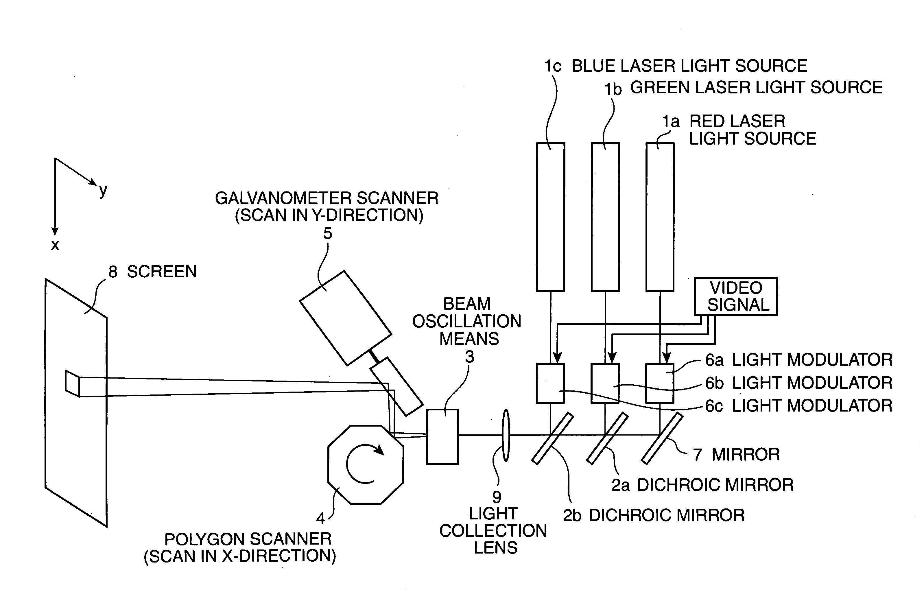
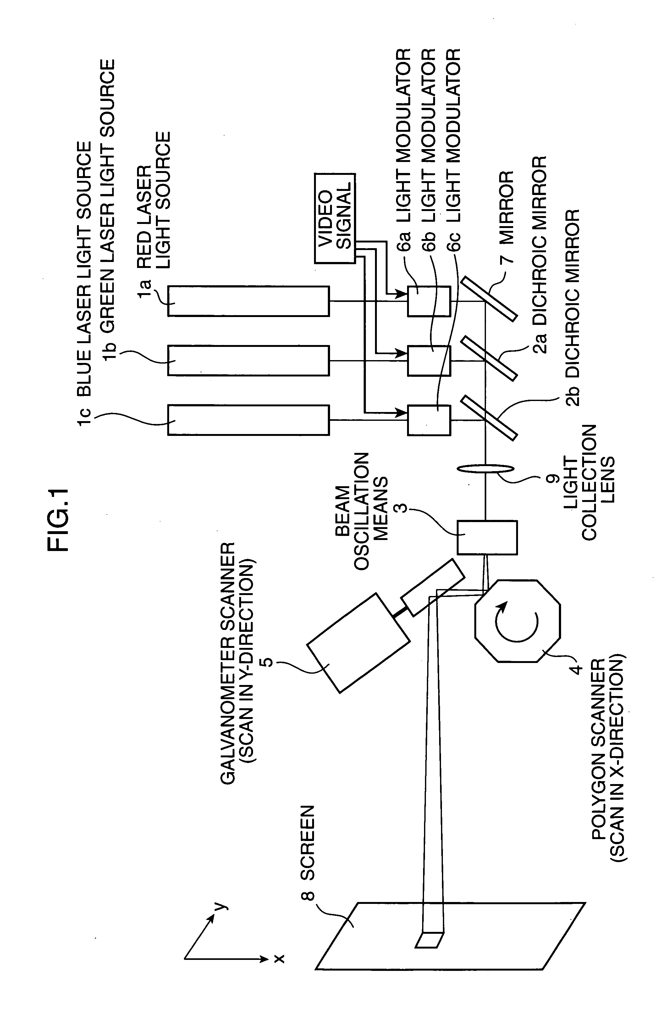
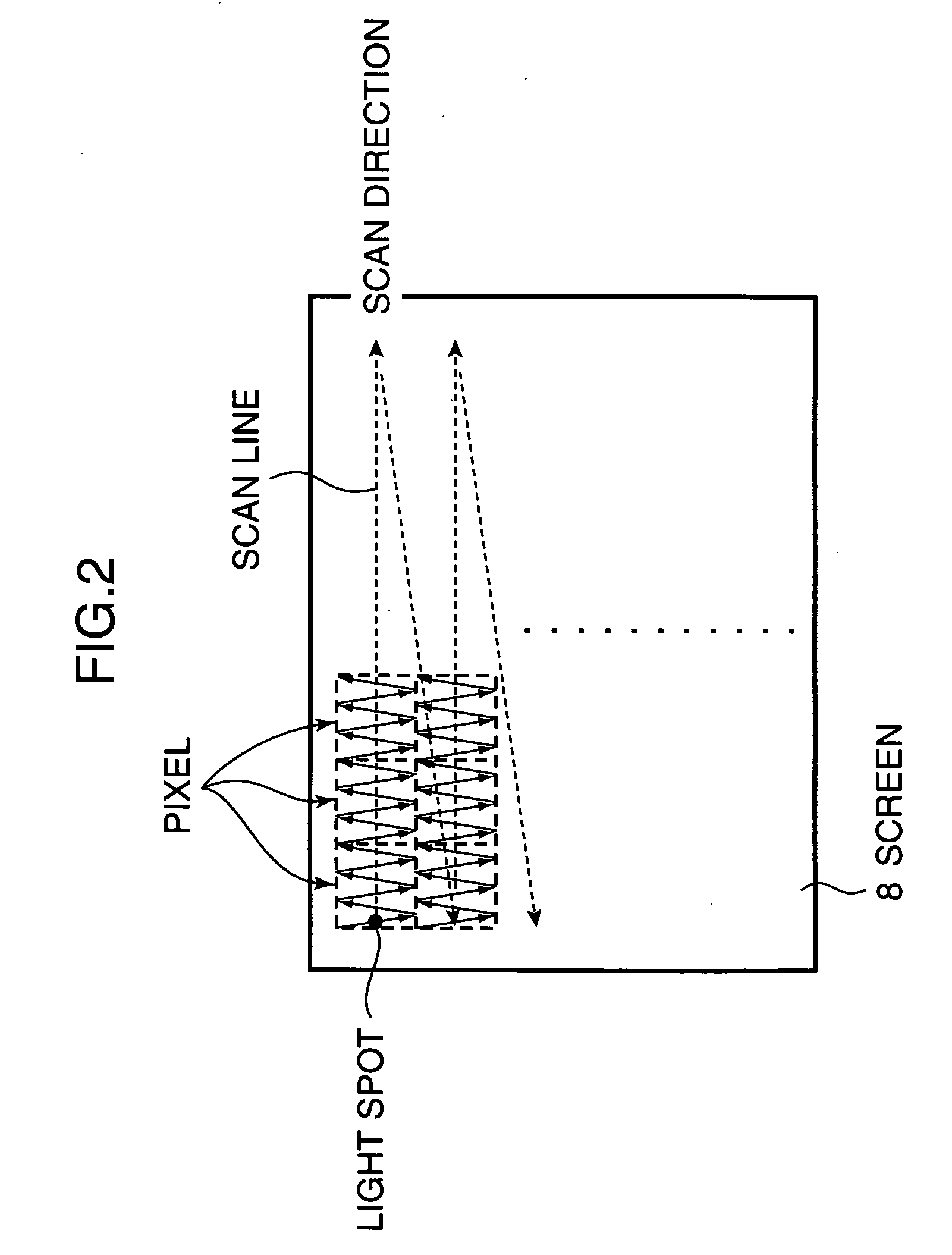
[0021]FIG. 1 is a view schematically showing the configuration of a 2-D image display device of the invention. Light beams emitted from a red laser light source 1a, a green laser light source 1b, and a blue laser light source 1c are modulated, respectively, by light modulators 6a, 6b, and 6c that modulate light according to a video signal, and then combined by dichroic mirrors 2a and 2b. Further, a light beam is deflected in the x-direction (horizontal scan) by a polygon scanner 4 and subsequently deflected in the y-direction (vertical scan) by a galvanometer scanner 5 to be projected onto a screen 8 in the form of a 2-D image. In this instance, light beams modulated by the light modulators 6a through 6c are oscillated minutely on the screen 8 by beam oscillation means 3. In this instance, the beam on the screen is collected by a light collection lens 9 to form a minute light spot. The size of the light spot is smaller than oscillation amplitude on the screen 8 by the beam oscillati...

second embodiment

[0035]FIG. 4 is a view schematically showing the configuration of a second embodiment of the 2-D image display device of the invention. The first embodiment above is configured in such a manner that light beams emitted from the red laser light source 1a, the green laser light source 1b, and the blue laser light source 1c are combined first, and then oscillated by the beam oscillation means 3. Different from the above configuration, in this embodiment, an infrared coherent light source 33b and wavelength conversion means 32b are used as a green light source, and green light alone is oscillated by beam oscillation means 3b. For example, a YAG laser having a wavelength of 1064 nm is used as the infrared coherent light source 33b, and a second harmonic generator device, in which the lithium niobate substrate has a cyclic polarization inversion structure, is used as the wavelength conversion means 32b. The wavelength conversion means 32b allows light having half the wavelength of light c...

third embodiment

[0040]FIG. 6 is a view schematically showing a third embodiment of the 2-D image display device of the invention. In this embodiment, infrared coherent light sources 33b and 33c and wavelength conversion means 32b and 32c are used as light sources for green and blue, respectively, and green light and blue light are oscillated by beam oscillation means 3b and 3c, respectively. The infrared coherent light source 33b, the wavelength conversion means 32b, and the beam oscillation means 3b are the same as their counterparts in the second embodiment above, and the description of these components is omitted herein.

[0041]For example, a semiconductor laser having a wavelength of 850 nm is used as the infrared coherent light source 33c, and a second harmonic generator device, in which the lithium niobate substrate has the cyclic polarization inversion structure same as that in the wavelength conversion means 32b, is used as the wavelength conversion means 32c. It should be noted, however, tha...


PUM

PropertyMeasurementUnit
wavelengthaaaaaaaaaa

Abstract

In a laser display that displays a video by scanning a beam from a laser light source two-dimensionally on a screen, the image quality being displayed is deteriorated markedly by speckle noises induced from coherency of the light source. A method for oscillating the screen to remove the speckles has problems that a large-scale device is necessary and the screen cannot be chosen without any restrain.A speckle pattern being generated is changed at a high speed by oscillating a light spot on the screen at a high speed using beam oscillation means 3, so that the viewer acknowledges time-mean image having no speckle noises.

Description

TECHNICAL FIELD[0001]The present invention relates to an image display device using a laser light source, such as a TV receiver and a video projection device, and to an illumination light source to project an image.BACKGROUND ART[0002]FIG. 7 is a view schematically showing the configuration of a laser display in the related art described in detail, for example, in Non-Patent Document 1. Light beams from laser light sources for three colors, RGB, are combined by dichroic mirrors 102a and 102b, and scanned in the horizontal direction by a polygon scanner 104 and in the vertical direction by a galvanometer scanner 105 to be irradiated onto a screen 108. In this instance, a video is displayed on the screen by modulating intensity by light modulators 106a through 106c according to an input video signal. For example, in order to display a moving image corresponding to an NTSC video signal, about 500 scan lines in the horizontal direction are displayed for 30 frames per second, and the num...

Claims


Application Information

Patent Timeline
Patent Type & Authority Applications(United States)
IPC IPC(8): G02B26/10G02F1/29F21V9/16G02B27/48G02F1/37H04N5/74H04N9/31
CPCG02B26/101H04N9/3129H04N5/74G02B27/48
Inventor KASAZUMI, KEN'ICHIMIZUUCHI, KIMINORIYAMAMOTO, KAZUHISA
Owner PANASONIC CORP
Why Eureka
Try Eureka