Check patentability & draft patents in minutes with Patsnap Eureka AI!

Spread illuminating apparatus

Inactive Publication Date: 2008-07-17
MINEBEAMITSUMI INC
View PDF2 Cites 22 Cited by
  • Summary
  • Abstract
  • Description
  • Claims
  • Application Information

AI Technical Summary

Benefits of technology

[0009]The present invention has been made in light of the circumstances described above, and it is an object of the present invention to provide a spread illuminating apparatus in which a hot spot is inhibited from occurring, whereby a bright area in front of an LED is eliminated thus preventing brightness non-uniformity.
[0015]Accordingly, in the spread illuminating apparatus according to the present invention, light emitted from the point light source can be efficiently utilized thereby enhancing the overall brightness across the light outlet surface, and at the same time the occurrence of a hot spot is inhibited thus improving the visual quality at the light inlet surface of the light conductor plate.

Problems solved by technology

On the other hand, a light reflector plate may be extended to cover below an LED in order to effectively utilize light emitted downward from the LED, but this can possibly cause a hot spot problem.

Method used


Image

  • Spread illuminating apparatus
  • Spread illuminating apparatus
  • Spread illuminating apparatus

Examples


second embodiment

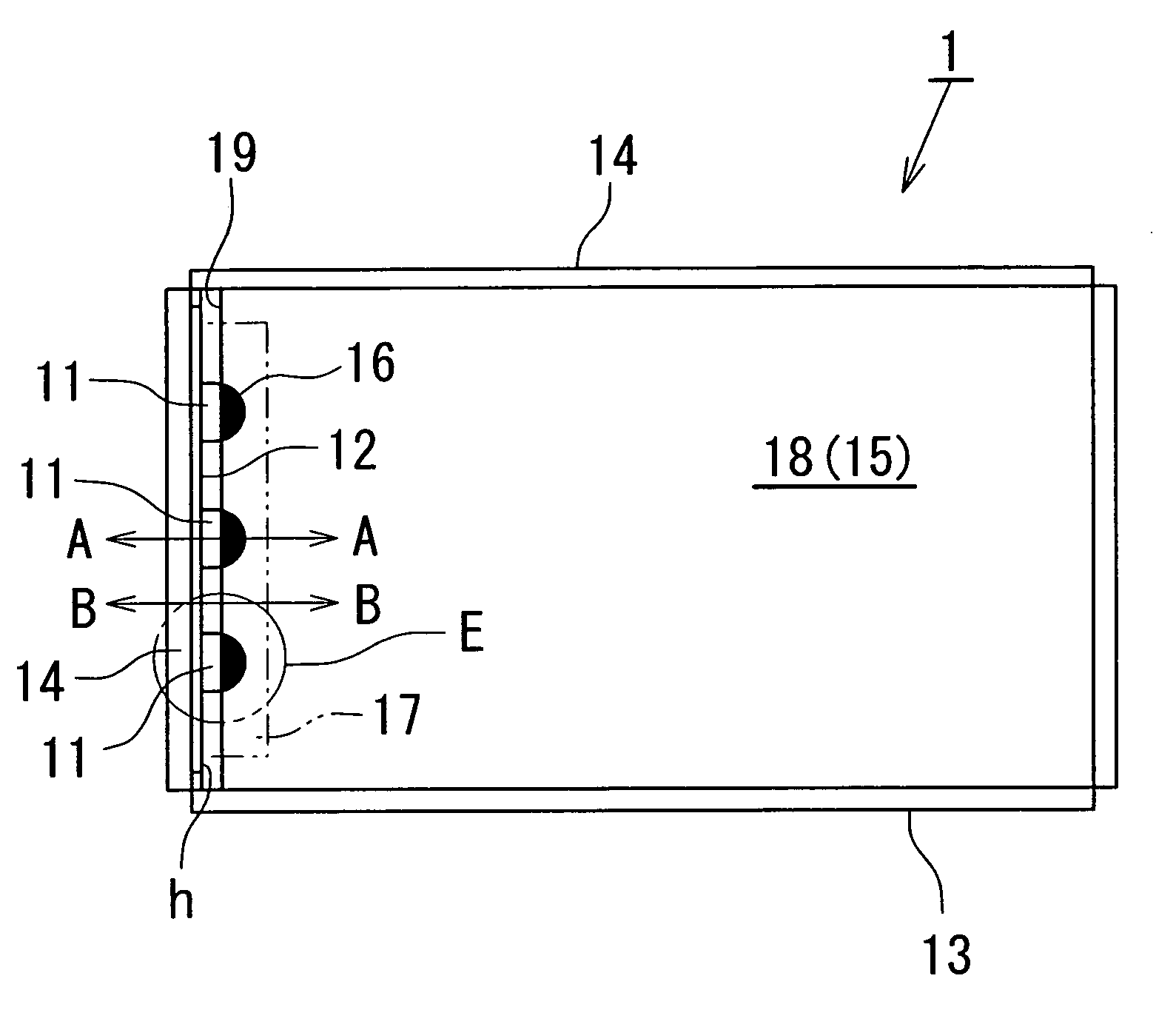
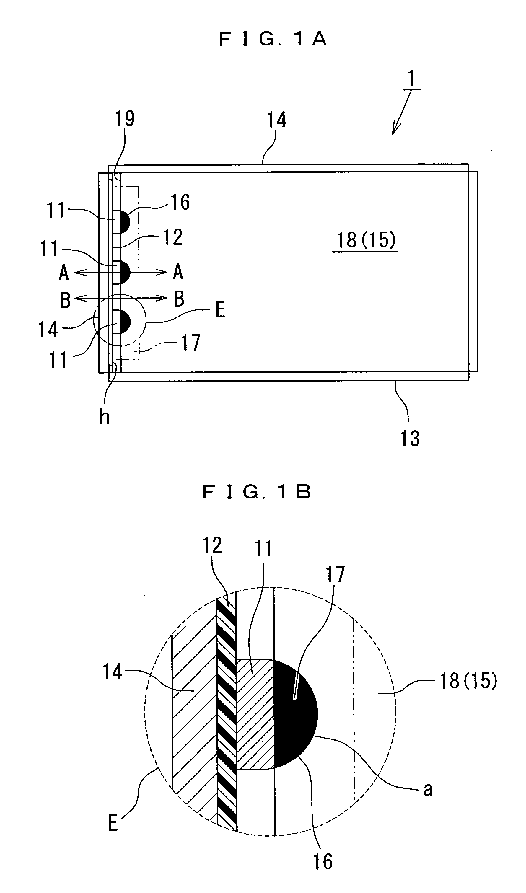
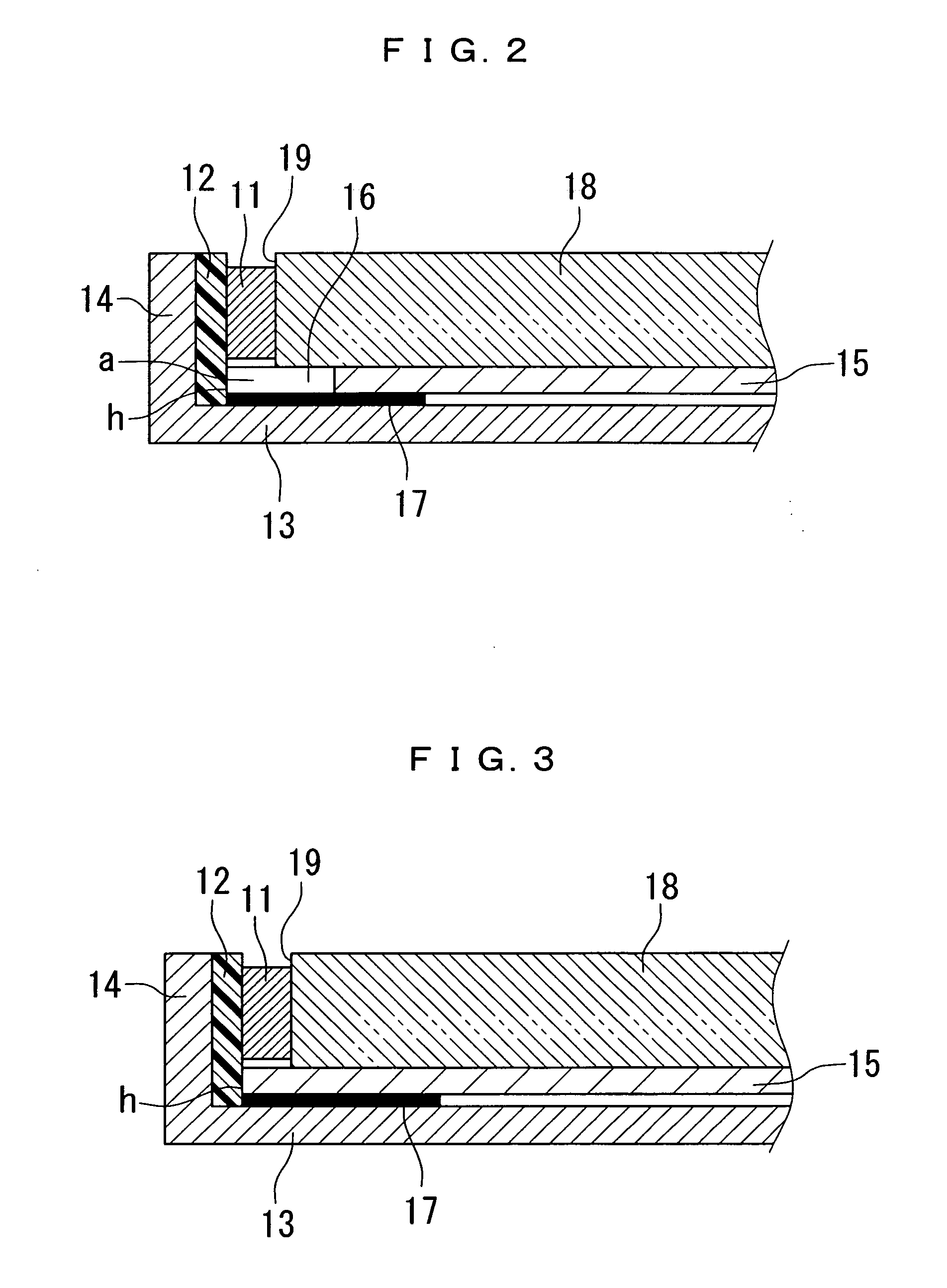
[0029]the present invention will now be described with reference to FIGS. 5 and 6. A spread illuminating apparatus 1A according to the second embodiment is structured basically the same as the spread illuminating apparatus 1 according to the first embodiment except the provision of a light diffuser sheet 20 on a light conductor plate 18, and a redundant description will be omitted below.

[0030]An end of the light diffuser sheet 20 located toward LEDs 11 is positioned beyond a light inlet surface 19 of the light conductor plate 18 (in the figures, the end reaches an FPC 12 on which the LEDs 11 are mounted), and recesses 21 having a semicircular shape are provided at the end of the light diffuser sheet 20 so as to correspond to respective LEDs 11 with each thereof covering above and in front of the LED 11.

[0031]With the structure described above, light beams emitted upwardly and laterally from the LED 11 are adapted to impinge on the light diffuser sheet 20 and have their optical paths...


PUM


Abstract

A spread illuminating apparatus includes LEDs as point light sources fixedly mounted on a flexible printed circuit, a light conductor plate having a light inlet surface, a light reflector plate disposed under the light conductor plate, a light absorbing member constituted by a black tape, and a sheet metal case having walls on all four sides and housing the component members described above. An end of the light reflector plate located toward the LEDs is positioned beyond the light inlet surface of the light conductor plate, and recesses are provided at the end of the light reflector plate. A black tape as a light absorbing member is disposed on the outer surface of the light reflector plate along the light inlet surface, and a light absorbing region is formed such that the black tape is exposed through the recess.

Description

BACKGROUND OF THE INVENTION[0001]1. Field of the Invention[0002]The present invention relates to a side light type spread illuminating apparatus, and more particularly to a spread illuminating apparatus which is used as a lighting means of a liquid crystal display device and in which a hot spot attributable to light coming from a light emitting diode as a light source is inhibited.[0003]2. Description of the Related Art[0004]A backlight system which irradiates a liquid crystal display (LCD) area from its behind has been conventionally used as a spread illuminating apparatus (a lighting means) for an LCD device. Such the spread illuminating apparatus (backlight system) includes a light conductor plate having light transmitting property, and a plurality of light emitting diodes (LEDs) or a cold cathode lamp as a light source disposed at a side surface of the light conductor plate, wherein light, which is emitted from the LED or the cold cathode lamp and introduced into the light condu...

Claims


Application Information

Patent Timeline
IPC IPC(8): F21V7/04
CPCG02B6/0023G02B6/0055G02B6/005
Inventor OHNO, YASUO
Owner MINEBEAMITSUMI INC
Features
  • R&D
  • Intellectual Property
  • Life Sciences
  • Materials
  • Tech Scout
  • Unparalleled Data Quality
  • Higher Quality Content
  • 60% Fewer Hallucinations
Learn More