Face hobbing or gear cutting head for cutting gears, such as spiral, bevel, spiral-bevel, and hypoid gears

a technology of gear cutting head and hobbing head, which is applied in the direction of gear teeth, manufacturing tools, gear-teeth manufacturing apparatus, etc., can solve the problem of high construction expenditur

Inactive Publication Date: 2008-07-17
KENNAMETAL INC
View PDF5 Cites 11 Cited by
  • Summary
  • Abstract
  • Description
  • Claims
  • Application Information

AI Technical Summary

Benefits of technology

[0011]A blade head design and method of securing blades within a blade head are provided in which blade holders or receptacles within a blade head are designed compleme...

Problems solved by technology

It is a general problem in the art that in all designs, additional cla...

Method used


Image

  • Face hobbing or gear cutting head for cutting gears, such as spiral, bevel, spiral-bevel, and hypoid gears
  • Face hobbing or gear cutting head for cutting gears, such as spiral, bevel, spiral-bevel, and hypoid gears
  • Face hobbing or gear cutting head for cutting gears, such as spiral, bevel, spiral-bevel, and hypoid gears

Examples


Embodiment Construction

[0020]In the figures, parts with the same functions are marked with the same reference or indicia numbers. Further, the terms “blade holder” and “blade holder receptacles” are both used to refer to a method and design for holding a blade in place on a blade head.

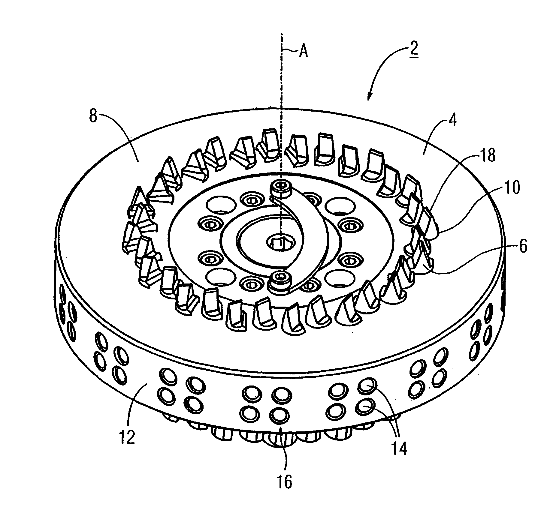
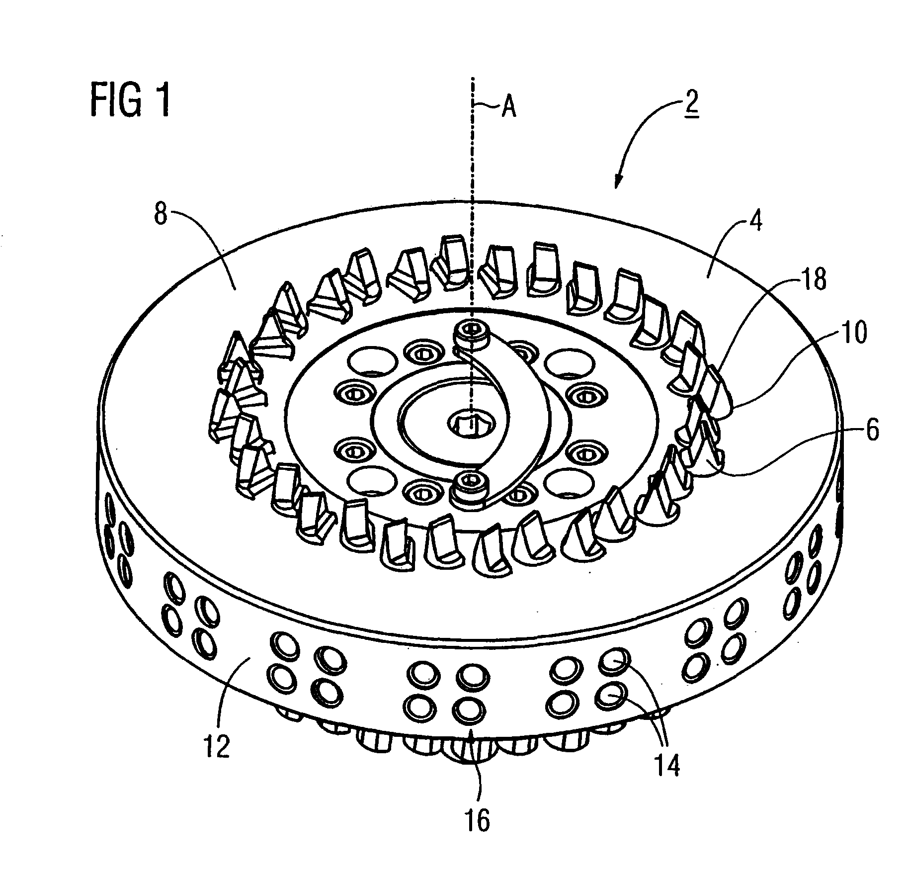
[0021]FIG. 1 shows a blade head or gear cutting head 2 comprising a disk-shaped, one-piece blade carrier 4 and a plurality of bar blades or cutter blades 6. The blade carrier 4 is rotatable about a disk rotation axis A. It comprises a machining side 8 with a plurality of blade holders 10, in which the bar blades 6 are held. The disk rotation axis A extends through the center M of the blade carrier 4. The blade holders 10 are arranged in pairs in a circle around the center M of the disk-shaped blade carrier 4. The blade holders 10 are formed by an electric discharge method and have a cross-section in the shape of the segment of a circle. Furthermore, the blade carrier 4 has a peripheral side 12 into which two rows of securing...


PUM

PropertyMeasurementUnit
Angleaaaaaaaaaa
Angleaaaaaaaaaa
Angleaaaaaaaaaa

Abstract

A face hobbing or gear cutting head for cutting gears, such as spiral, bevel, and hypoid gears which has a blade carrier for holding cutter blades. The abstract of the disclosure is submitted herewith as required by 37 C.F.R. §1.72(b). As stated in 37 C.F.R. §1.72(b): A brief abstract of the technical disclosure in the specification must commence on a separate sheet, preferably following the claims, under the heading “Abstract of the Disclosure.” The purpose of the abstract is to enable the Patent and Trademark Office and the public generally to determine quickly from a cursory inspection the nature and gist of the technical disclosure. The abstract shall not be used for interpreting the scope of the claims. Therefore, any statements made relating to the abstract are not intended to limit the claims in any manner and should not be interpreted as limiting the claims in any manner.

Description

[0001]This application is a Continuation-In-Part application of International Patent Application No. PCT / EP2006 / 004646, filed on May 17, 2006, which claims priority from Federal Republic of Germany Patent Application No. 10 2005 032 761.3, filed on Jul. 14, 2005. International Patent Application No. PCT / EP2006 / 004646 was pending as of the filing date of this application. The United States was an elected state in International Patent Application No. PCT / EP2006 / 004646.BACKGROUND[0002]1. Technical Field[0003]This application relates to a face hobbing or gear cutting head for cutting gears, such as spiral, bevel, and hypoid gears. This application further relates generally to blade heads and more specifically to a blade head design for indenting spiral bevel gears processing systems and the like.[0004]2. Background Information[0005]Face hobbing machines usually comprise cutting blades arranged about a cutter, not in line with each other, but in groups, usually pairs comprising an inner ...

Claims


Application Information

Patent Timeline
IPC IPC(8): B23P15/34
CPCY10T407/1735B23F21/226
Inventor MUHLFRIEDEL, DIETER
Owner KENNAMETAL INC
Why Eureka
Try Eureka