

Glove iron
- Summary
- Abstract
- Description
- Claims
- Application Information
AI Technical Summary
Benefits of technology
Problems solved by technology
Method used
Image

Examples
first embodiment
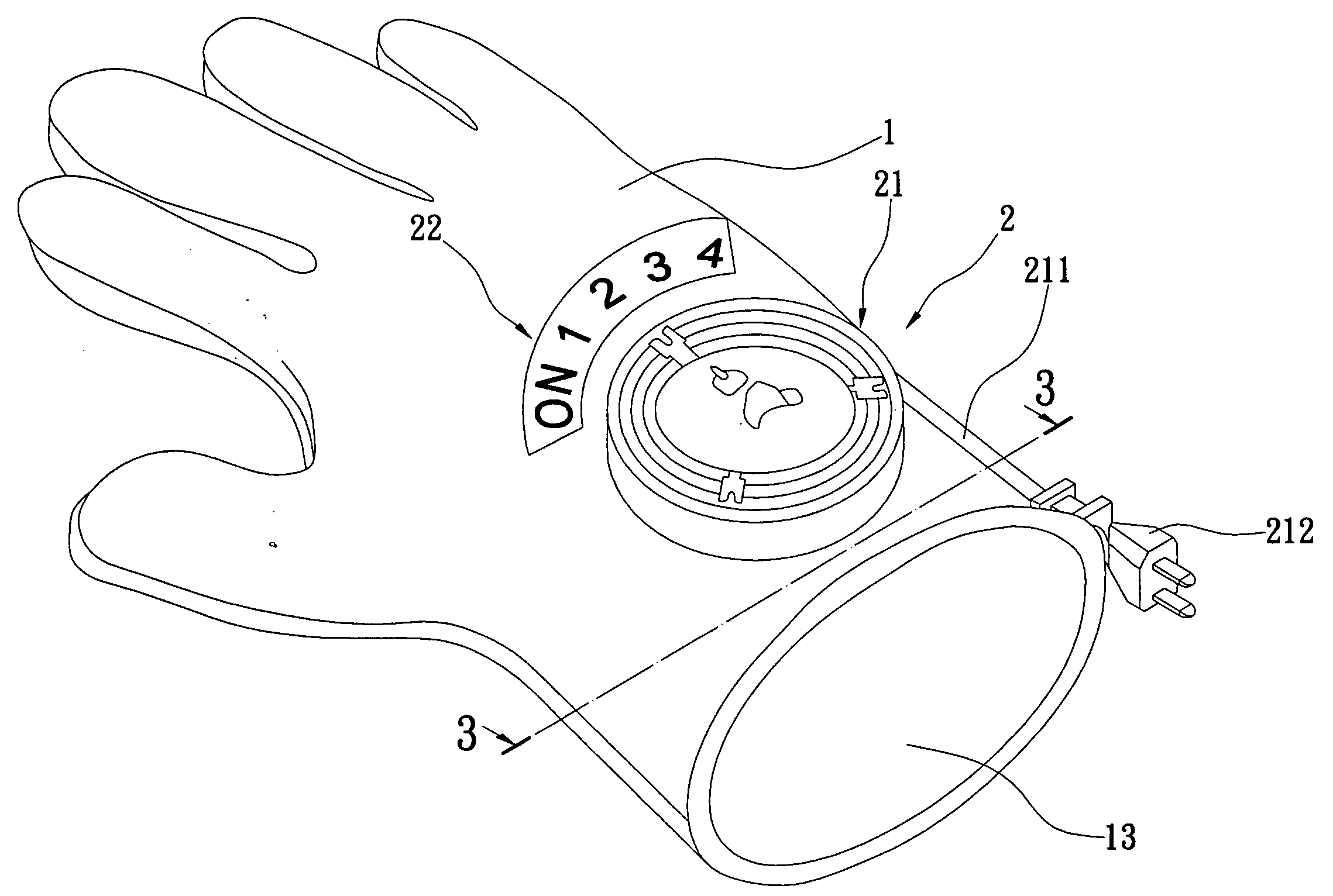
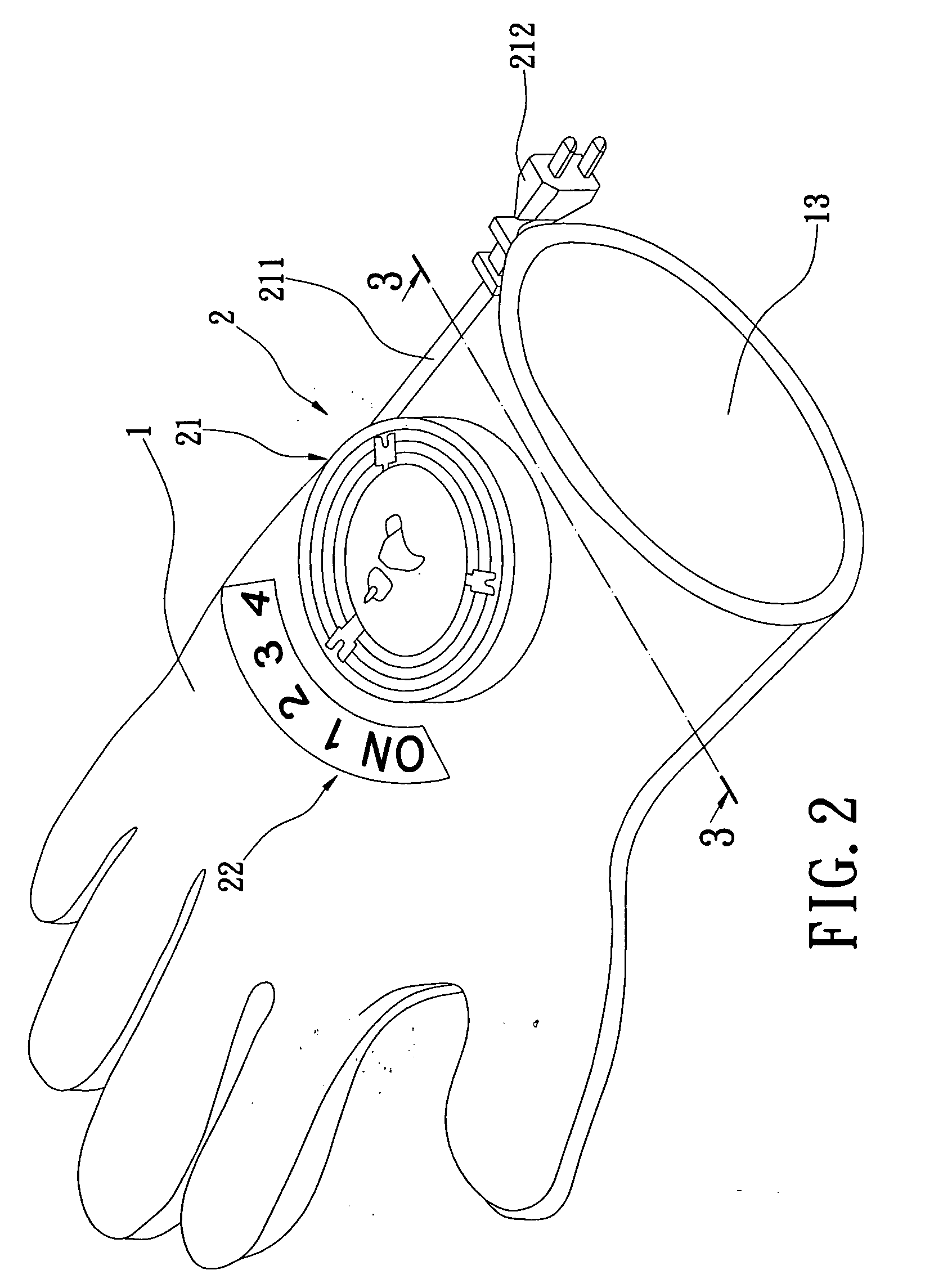
[0038]The reel structure 21 has a reel module 211 and a plug 212 connected to the reel module 211. The reel module 211 can be wound or unwound to retract or draw the plug 212. The controller 22 is used to adjust the magnitude of heat generation of the cloth body 1. A user can thus utilize the reel structure 21 to make the cloth body 1 to generate heat. Moreover, the reel structure 21 can be wound up to occupy less space when not in use. FIG. 5 is a perspective view according to the power unit of the glove iron of the present invention. As shown in FIG. 5, the power unit 2 is a battery power module. When the power unit is disposed on the cloth body 1 as shown in FIG. 3, the power unit 2 has a battery holder 23 electrically connected to the electrothermal fiber layer 12 and a battery 24 disposed on the battery holder 23. When the power unit 2 is disposed on the cloth body 1 as shown in FIG. 4, the power unit 2 has a battery holder 23 electrically connected to the electrothermal membra...
second embodiment
[0039]FIG. 6 is a perspective view according to the power unit of the glove iron of the present invention. As shown in FIG. 6, the power unit 2 is a combinational power module. When the power unit 2 is disposed on the cloth body 1 as shown in FIG. 3, the power unit 2 has a plug power structure electrically connected to the electrothermal fiber layer 12 and a battery power structure electrically connected to the plug power structure. The plug power structure has a reel structure 21A electrically connected to the electrothermal fiber layer 12 and a controller 22A for controlling the reel structure 21A. The battery power structure has a battery holder 23A electrically connected to the electrothermal fiber layer 12 and a battery 24A disposed on the battery holder 23A. When the power unit is disposed on the cloth body 1 as shown in FIG. 4, the power unit 2 has a plug power structure electrically connected to the electrothermal membrane 12A and a battery power structure electrically conne...
PUM
 Abstract
Description
Claims
Application Information