Eureka AIR delivers breakthrough ideas for toughest innovation challenges, trusted by R&D personnel around the world.

Cable-stripping pliers

Active Publication Date: 2008-07-24
CHANNELLOCK
View PDF31 Cites 5 Cited by
  • Summary
  • Abstract
  • Description
  • Claims
  • Application Information

AI Technical Summary

Benefits of technology

[0009]The present pliers readily strips resilient polymeric insulation from a cable having core metal material. The pliers, in one principal aspect includes a first member having a handle and a jaw, a second member having a handle and a jaw, and means for pivotably connecting the members so that the handles close the jaws on the resilient insulation, and at least one jaw has oppositely disposed arcuate surfaces and an cutting edge formed at the end of the arcuate surfaces, so that with the jaws closed on the cable the cutting edge cuts the insulation away from the core material. In a further aspect, both jaws comprise like arcuate surfaces with like cutting edges, and the cutting edges are facingly disposed with the jaws closed. Each cutting edge is formed by opposite disposed arcuate contoured surfaces. The cutting edges are themselves arcuate. The arcuate surfaces are transversely disposed to the respective arcuate cutting edge. The cutting edges in cutting the insulation cause the insulation to be spacingly disposed from the arcuate surface of the pliers and permits readily stripping the insulation.

Problems solved by technology

The prior art cable stripping pliers, in cutting resilient insulation, does not generally provide sufficient means readily the insulation so as to prevent cutting of the core metal.
The prior art cable stripping pliers were also generally of complex design, construction and operation.

Method used


Image

  • Cable-stripping pliers
  • Cable-stripping pliers
  • Cable-stripping pliers

Examples


Embodiment Construction

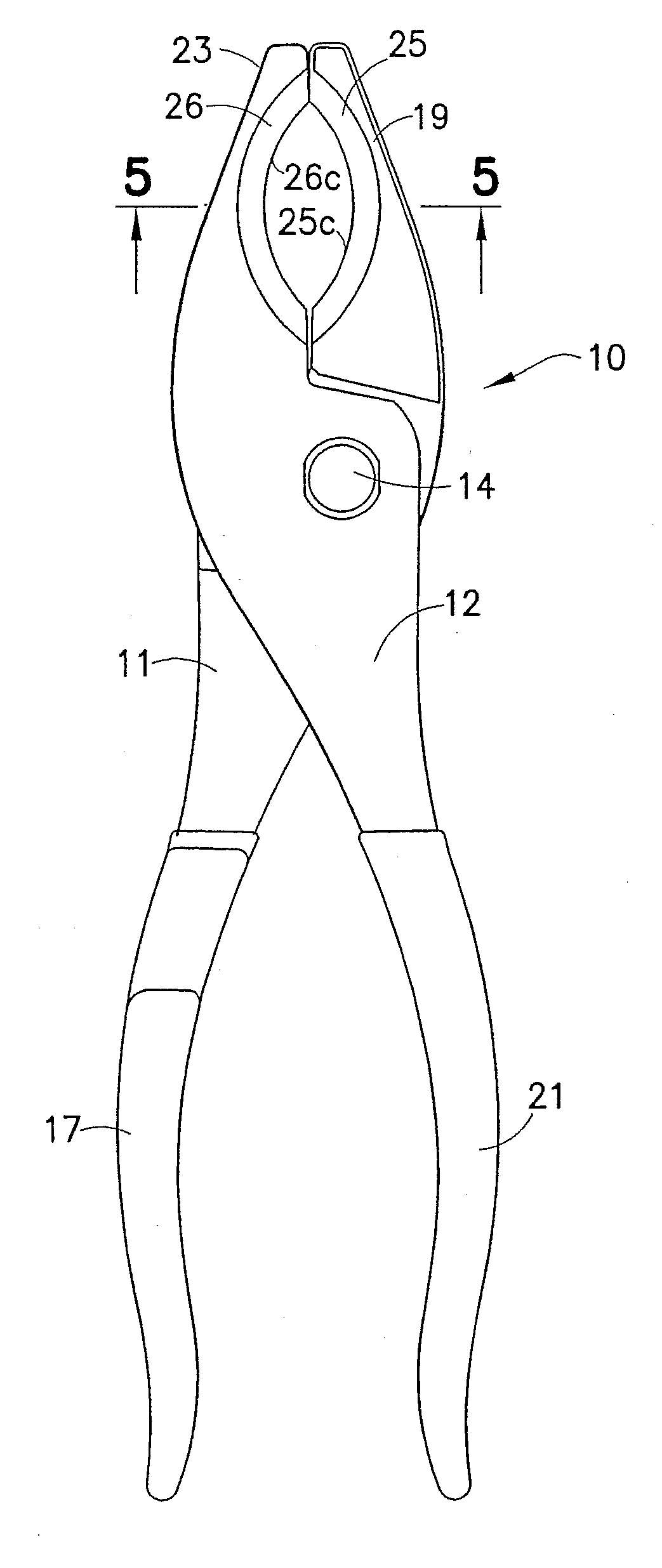
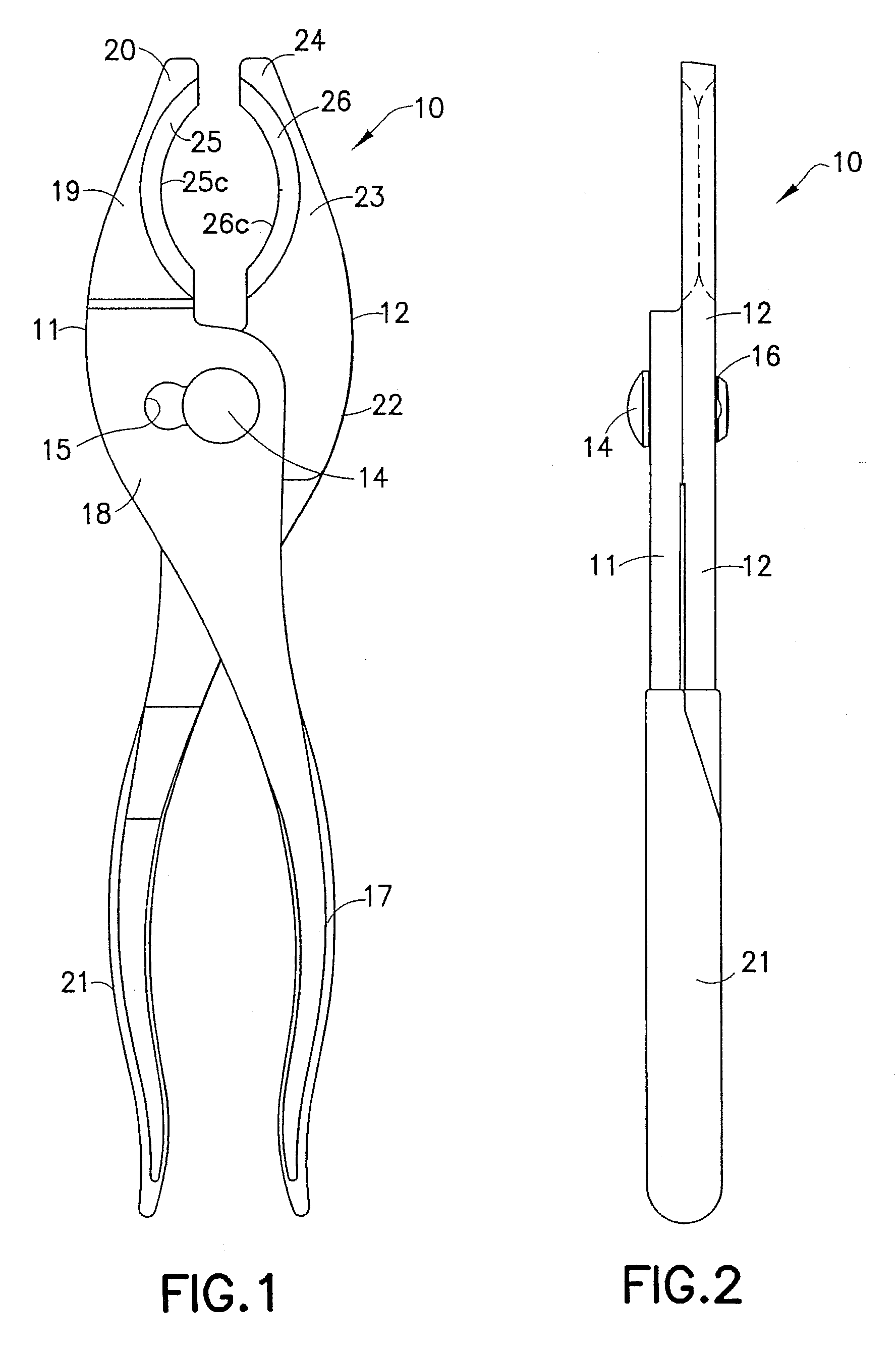
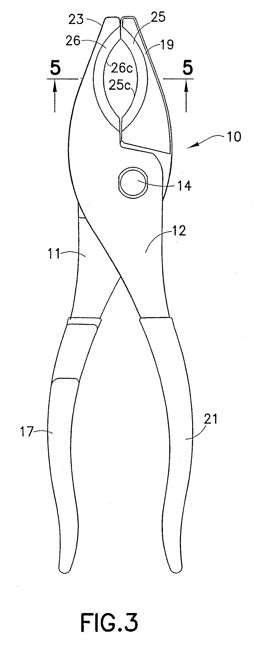
[0016]Referring to the FIGS., there is shown the cable-stripping pliers 10 of the present invention. Pliers 10 include a first member 11 and a second member 12, and a two-position adjustable pivot assembly 13 for pivotably connecting members 11 and 12. Pivot assembly 13 includes pivot pin 14 and a two-lobe through hole 15. Through hole 15 slidably rotatably receives pivot pin 14. The two-mode or two-position adjustable pivot permits the jaws, in a first mode to cut the insulation for cables up to about 1½ inches in diameter, and in the second mode cut insulation for cables up to ¾ inch in diameter, without cutting into the core material.

[0017]Member 11 includes grip handle 17, intermediate portion 18, jaw 19 and distal end 20. Member 11 is of one-piece integral hardened steel construction. Intermediate portion 20 formed with through hole 15. Member 12 includes grip handle 21, intermediate portion 22, jaw 23 and distal end portion 24. Member 12 of one-piece integral hardened steel co...


PUM

PropertyMeasurementUnit
Angleaaaaaaaaaa
Resilienceaaaaaaaaaa

Abstract

A cable stripping pliers has facingly disposed arcuate cutting edges formed at the ends of transversely oppositely disposed arcuate surfaces. The pliers are adjustable to two positions for the jaws to engage differently sized cables. The resilient insulation is disposed away from the arcuate surfaces when the cutting edges cut the resilient insulation for readily removing the insulation from the core material.

Description

BACKGROUND OF THE INVENTION[0001]1. Field of the Invention[0002]The present invention relates to cable-stripping pliers. The present invention particularly relates to pliers for cutting resilient cable insulation and stripping the insulation from the cable core material.[0003]2. Background and Discussion of the Prior Art[0004]Insulation stripping pliers are generally known in the art. Typical cable insulation stripping pliers are disclosed in U.S. Pat. No. 4,407,174, granted Oct. 4, 1983 to Schulz and U.S. Pat. No. 4,112,791 granted Sep. 12, 1978 to Werner. Such prior art cable stripping pliers require spring and cam mechanisms to provide the necessary movement of the stripping jaws for cutting and stripping the insulation. The stripping jaws edges were generally elongate straight with acutely angled cutting edges.[0005]Prior art cable insulation stripping pliers were generally constructed with diverse sized cutting edges and a single pivot axis, such as disclosed in U.S. Pat. No. 6...

Claims


Application Information

Patent Timeline
IPC IPC(8): H02G1/12H02G1/00
CPCH02G1/1224
Inventor FARRELL, TERRY C.
Owner CHANNELLOCK
Why Eureka
Eureka Blog
Learn More