Canopy with illumination device

a technology of illumination device and canopy, which is applied in the field of canopies, can solve the problems of easy damage to illumination devices, and damage to power supplies usually associated with illumination devices, and achieves uniform and extensive illumination, high power consumption of light bulbs or filament bulbs, and pleasant effects for users

Inactive Publication Date: 2008-07-24
ZHEJIANG YOTRIO GRP CO LTD
View PDF20 Cites 23 Cited by
  • Summary
  • Abstract
  • Description
  • Claims
  • Application Information

AI Technical Summary

Benefits of technology

[0035]In general, that embodiment of the invention is preferred in which the illumination device comprises one or more illumination elements. This usually helps the illumination cover a large surface area by illumination. A plurality of illumination elements can be distributed in a decentralized manner in the support structure of the canopy, thereby ensuring more uniform and extensive illumination. However, it is also possible to use a single illumination element as the illumination device.
[0036]The illumination elements can comprise filament bulbs, light bulbs, and / or light-emitting diodes (LEDs). The advantage of filament bulbs or light bulbs is that they emit light that has particularly pleasant effects for the user. However, the power consumption of light bulbs or filament bulbs is known to be high as compared to the light output emitted. The advantage of light-emitting diodes is that they require only a very small volume inside the support structure of the apparatus. Moreover, the heat capacity of light-emitting diodes is very low since a large part of the power consumed is converted into light output. Therefore, light-emitting diodes generally consume very less power as compared to light bulbs. The small overall size of LEDs makes it possible to arrange many light-emitting diodes inside the support structure of the canopy according to the invention. Furthermore, the variably colored light-emitting diodes help achieve all kinds of light effects. The light output can be regulated by selectively switching on and off the light-emitting diodes. This also enables a reduction in the power consumption of the illumination device.

Problems solved by technology

However, these category-defining canopies suffer from shortcomings in several respects.
Firstly, the illumination device disposed on the outer side of the support structure is very susceptible to damage.
Such damages result almost inevitably when a canopy must or should be mounted and dismantled regularly.
In these cases, the illumination device, and the power supply usually associated therewith can sustain damage as a result of the user's carelessness or an unavoidable collision with other components of the canopy.
The possible breakage of glass poses an increased risk of injury.
Furthermore, another disadvantage of the category-defining canopies is that the illumination device disposed on the outer side of the support structure can pose an increased risk of injury during the operation of the illuminable canopy.
Thus, an unwary user or a child may accidentally touch the possibly very hot parts of the illumination device and sustain considerable injuries.
These insects get caught up in parts of the illumination device or perish on coming into contact with the hot parts of the illumination device, which in a short time stains the illumination device, and thus the entire canopy.

Method used


Image

  • Canopy with illumination device
  • Canopy with illumination device
  • Canopy with illumination device

Examples


Embodiment Construction

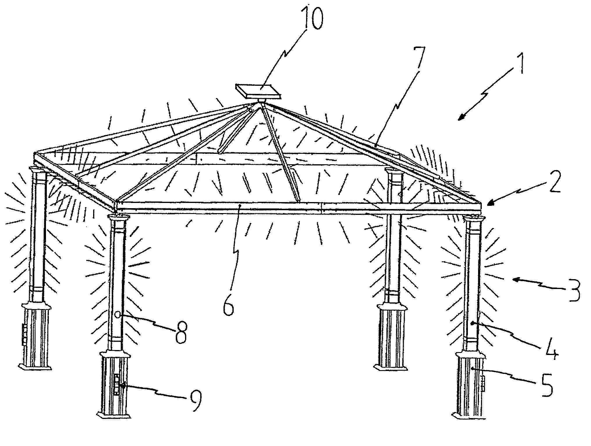
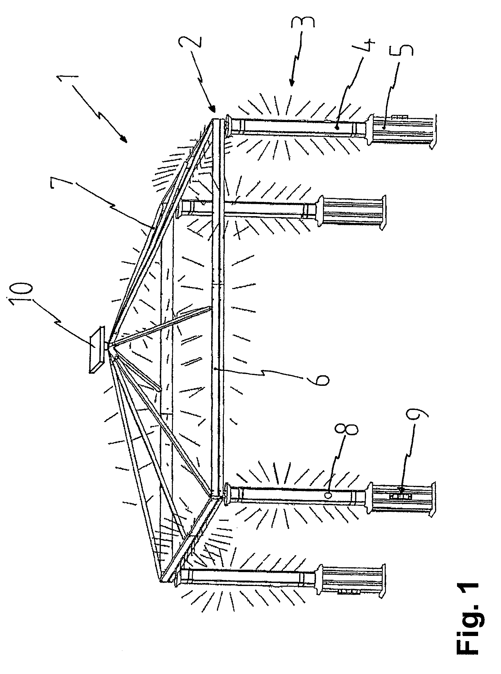
[0052]FIG. 1 shows a side view of a canopy 1 according to the invention. The canopy is designed in this exemplary embodiment as a pavilion, as is used in gardens or recreational areas by way of example. For purposes of clarity, the roof of the pavilion is not shown in this figure. The roof can be formed, in the usual manner, of a plastic film or any other material already mentioned above.

[0053]The canopy 1 comprises a support structure 2 for the roof and an illumination device 3 associated with the support structure 2. In this example, the support structure 2 comprises support braces 4. Those ends of the support braces that are located close to the ground form a base 5. The pavilion comprises altogether four support braces 4, which are disposed vertically and form the vertices of a rectangle. The upper ends of the support braces 4 are connected by means of horizontally disposed cross-braces 6.

[0054]At least four roof braces 7, which connect the vertices of the rectangle to the cente...


PUM


Abstract

A canopy, particularly a pavilion, a pergola, a tent or an awning, having a roof, a support structure for the roof and an illumination device associated with the support structure, is characterized, with regard to the object of achieving reliable operation of the apparatus, a particularly appealing visual impression and the greatest possible protection for the illumination device, in that the illumination device is associated with the support structure essentially integrally.

Description

CROSS-REFERENCE TO RELATED APPLICATIONS[0001]The present application is a Continuation of International Application No. PCT / DE2006 / 000548, filed Mar. 28, 2006, and which designates the U.S. The disclosure of the referenced application is incorporated herein by reference.FIELD OF THE INVENTION[0002]The present invention relates to a canopy, in particular a pavilion, a pergola, a tent or an awning, said canopy comprising a roof, a support structure for the roof, and an illumination device associated with the support structure.BACKGROUND OF THE INVENTION[0003]The German Utility Model Patent Application DE 90 04 867 U1 discloses a low-voltage illumination device for pergola systems. The illumination device consists of low-voltage illumination elements disposed on the outer side of the support structure of the pergola.[0004]Furthermore, pavilion-like structures are known from the prior art, which structures also comprise a roof supported by the support structure. These canopy systems lik...

Claims


Application Information

Patent Timeline
Patent Type & Authority Applications(United States)
IPC IPC(8): E04H15/10
CPCE04F10/00E04H1/1272E04H15/10Y02B10/12F21S9/03F21V33/008F21Y2101/02F21S9/02F21Y2115/10Y02B10/10
Inventor FALIN, ZHAO
Owner ZHEJIANG YOTRIO GRP CO LTD
Why Eureka
Try Eureka