Fast low dropout voltage regulator circuit

a voltage regulator and low dropout technology, applied in the direction of electric variable regulation, process and machine control, instruments, etc., can solve the problems of deteriorating the transient response of the ldo regulator, wasting valuable current, and affecting the efficiency of light load

Inactive Publication Date: 2008-07-24
DECICON A CALIFORNIA CORP
View PDF53 Cites 108 Cited by
  • Summary
  • Abstract
  • Description
  • Claims
  • Application Information

AI Technical Summary

Problems solved by technology

Minimizing the input-output voltage differential would require lowering of the supply voltage of the internal circuitry in LDO regulator 10 to a level close to the regulated output voltage, which in turn, poses a significant design challenge as lower output voltages are demanded from the output of the LDO regulator 10.
Such a biasing scheme wastes valuable current at light loads and the light load efficiency suffers as a result.
Another conventional approach is to keep the bias currents constant at a low to moderate level, but such an approach deteriorates the transient response of the LDO regulator.

Method used


Image

  • Fast low dropout voltage regulator circuit
  • Fast low dropout voltage regulator circuit
  • Fast low dropout voltage regulator circuit

Examples


Embodiment Construction

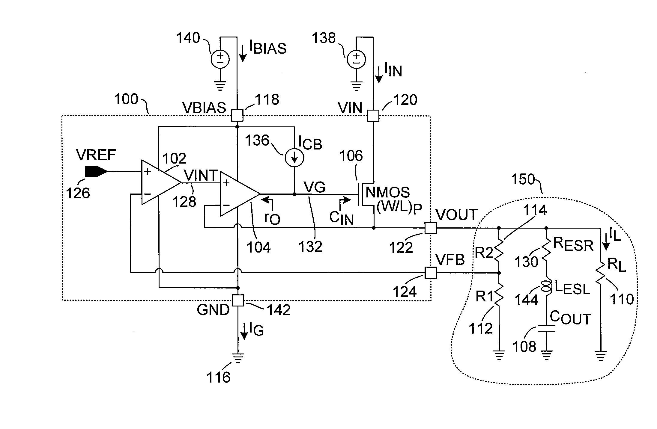
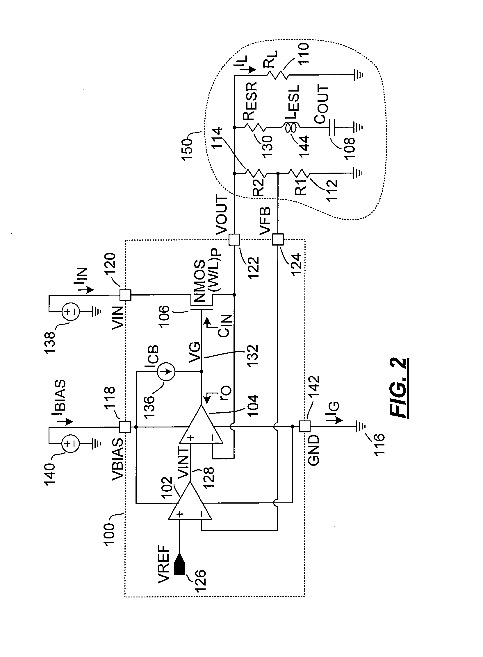
[0024]FIG. 2 is a block diagram of a low drop-out (LDO) linear integrated circuit 100, in accordance with one embodiment of the present invention. LDO 100 is shown as including amplifiers 102, 104, N-type pass element 106, and current source 136. Amplifiers 102 and 104 form a dual-feedback loop control circuit adapted to regulate output voltage VOUT delivered to output node 122. The following description is provided with reference to an NMOS transistor 106. It is understood that any N-type transistor, such as a bipolar NPN transistor, may also be used.

[0025]Amplifier 102 is a high-gain low-bandwidth amplifier (HGLBA) forming a relatively slower feedback loop (SFL) adapted to control the DC accuracy of regulator 100. Amplifier 104 is a low-gain, high-bandwidth amplifier (LGHBA) that together with NMOS transistor 106 form a fast and high current unity gain voltage follower. Amplifier 104 forms a fast feedback loop (FFL) adapted to maintain output voltage VOUT within a predefined range...


PUM


Abstract

A voltage regulator includes first and second closed-loop amplifiers and a N-type transistor. The first amplifier receives a first reference voltage and a feedback voltage. The second amplifier is responsive to the first amplifier and to the regulated output voltage of the regulator. Both amplifiers are biased by a biasing voltage. The second amplifier has a bandwidth greater than the bandwidth of the first amplifier and a gain smaller that the gain of the first amplifier. The N-type transistor has a first terminal responsive to the output of the second amplifier, a second terminal that receives the input voltage being regulated, and a third terminal that supplies the regulated output voltage. The feedback voltage is generating by dividing the regulated output voltage. An optional fixed or dynamically biased current source biases the first terminal of the N-type transistor. The voltage regulator optionally includes an overshoot correction circuit.

Description

CROSS-REFERENCES TO RELATED APPLICATIONS[0001]The present application claims benefit under 35 USC 119(e) of U.S. provisional Application No. 60 / 865,628, filed Nov. 13, 2006, entitled “Fast Low Dropout Voltage Regulator Circuit,” the content of which is incorporated herein by reference in its entirety.BACKGROUND OF THE INVENTION[0002]Low Drop-Out (LDO) linear voltage regulator integrated circuits are widely used in electronic systems, particularly in applications which require power supplies with low noise and low ripple. In portable applications, LDO regulators supply power to the analog baseband stages, radio frequency stages and to other noise-sensitive analog circuit blocks.[0003]The efficiency and the physical size of the power supply solution are two important aspects in portable applications where the amount of energy stored in the battery is limited and board space is at a premium. The efficiency loss of an LDO regulator has two principal components, namely thermal dissipatio...

Claims


Application Information

Patent Timeline
Patent Type & Authority Applications(United States)
IPC IPC(8): G05F1/575
CPCG05F1/575
Inventor GURCAN, HAKAN ATESOKYAR, MURAT MEHMET
Owner DECICON A CALIFORNIA CORP
Why Eureka
Try Eureka