Passive tracking antenna system

a tracking antenna and passive technology, applied in the field of passive tracking antenna systems, can solve the problems of omni-antennas, limited operating range, obvious movement parts,

Inactive Publication Date: 2008-07-24
WEINSTEIN ELIAHU +1
View PDF0 Cites 12 Cited by
  • Summary
  • Abstract
  • Description
  • Claims
  • Application Information

AI Technical Summary

Benefits of technology

[0005]The primary advantage of this invention is to provide a tracking antenna system that extends the range of wireless mobile links to 16 to 256 times the range of regular omni-directional whip antennas.

Problems solved by technology

The omni antenna has many disadvantages, for example low gain, which limits the operating range, susceptibility to jamming and interference, etc.
Moving parts have their obvious disadvantages, for example, wear and tear of the moving parts and a maintenance schedule for replacing worn parts.
Moreover, moving parts require significantly more power to drive their movement.
Therefore, there is a current need for a passive tracking antenna system for use between unmanned air, ground, and surface vehicles to mobile ground stations in motion, as well as between flying planes, moving vehicles, sailing boats, and combinations thereof, that extends the range of wireless mobile links, reduces the EMI signature of the links, limits the possibility of tracking and jamming of the links, and has direction finding capabilities without the need for GPS.

Method used


Image

  • Passive tracking antenna system
  • Passive tracking antenna system
  • Passive tracking antenna system

Examples


Embodiment Construction

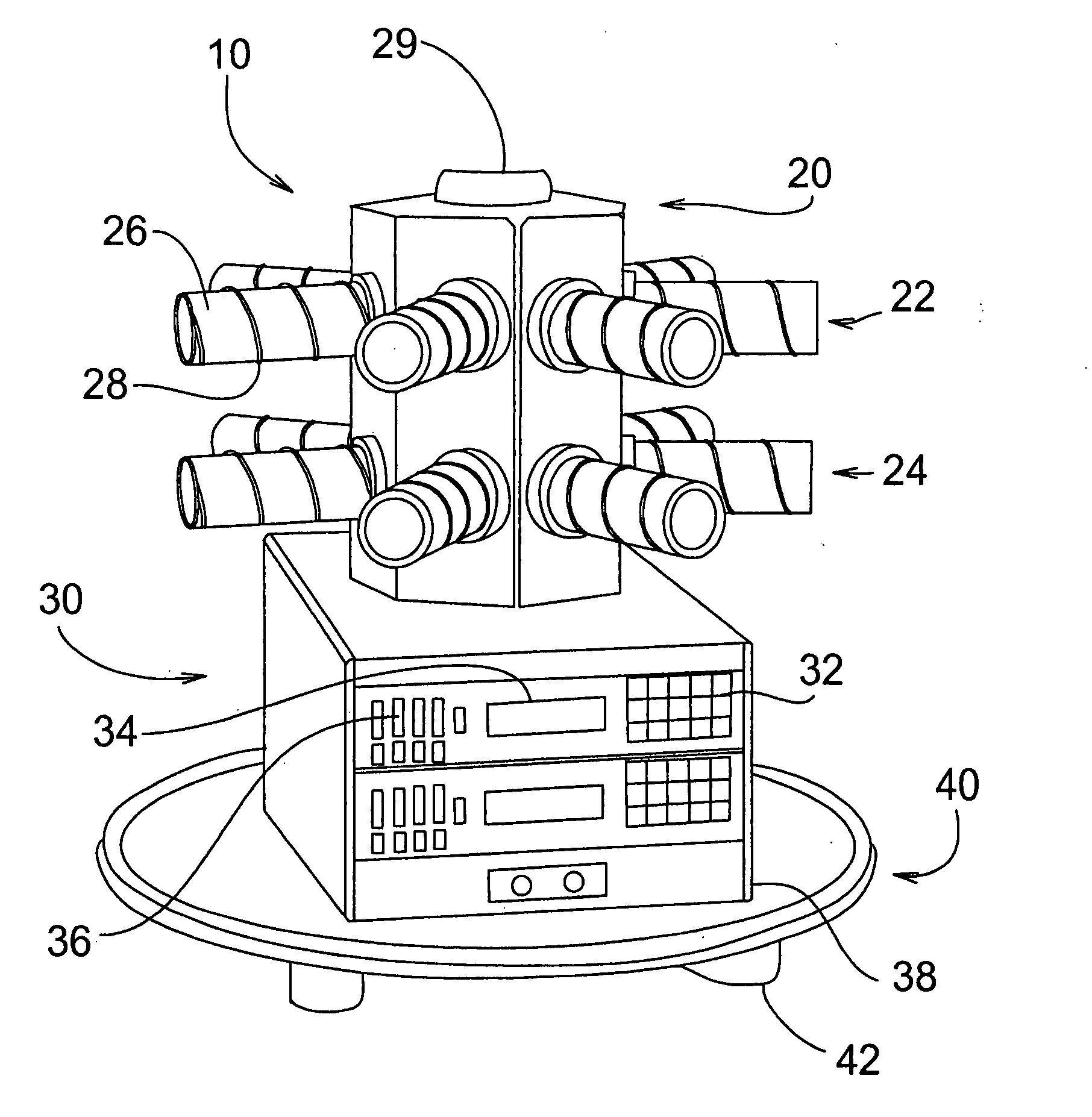
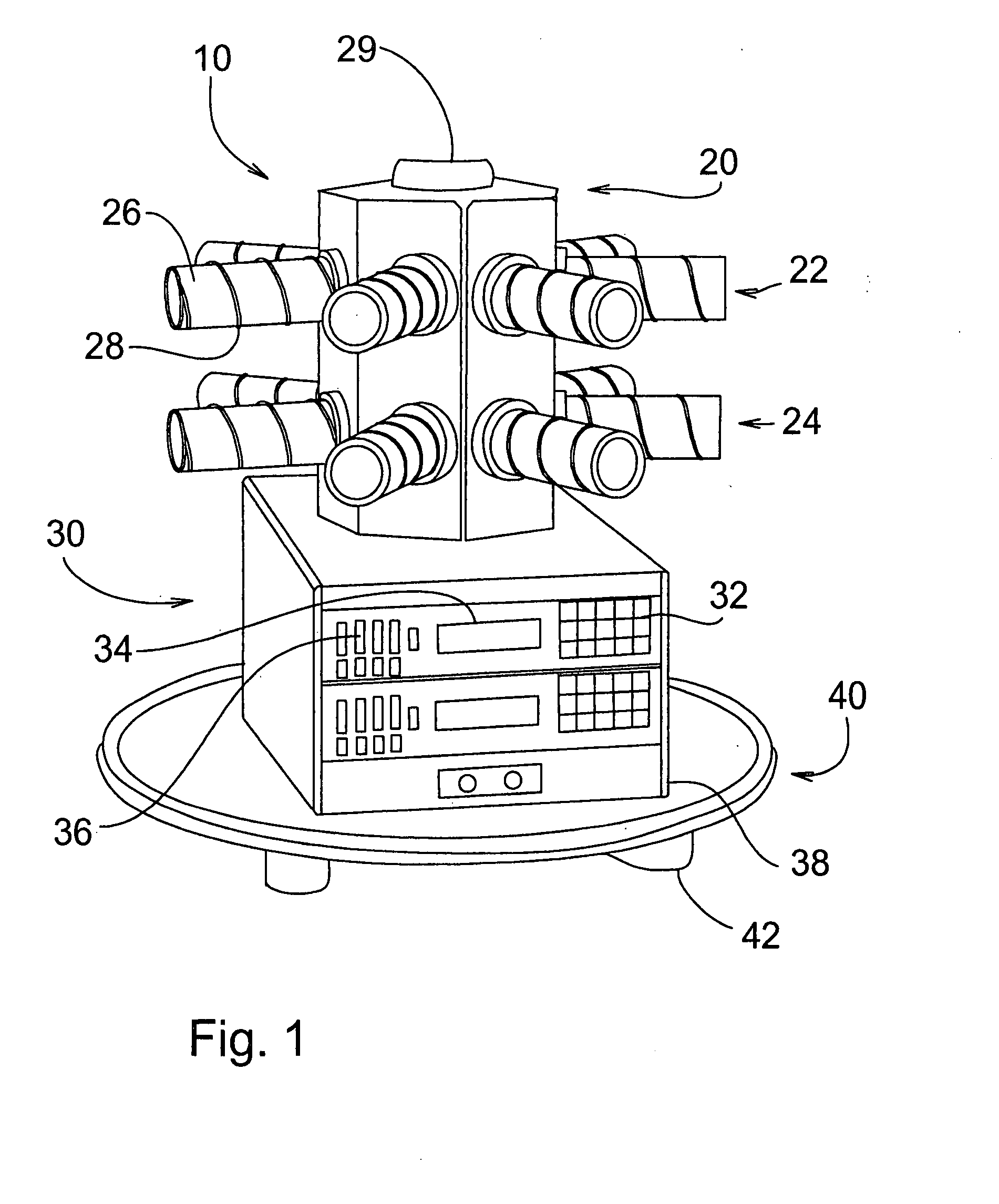
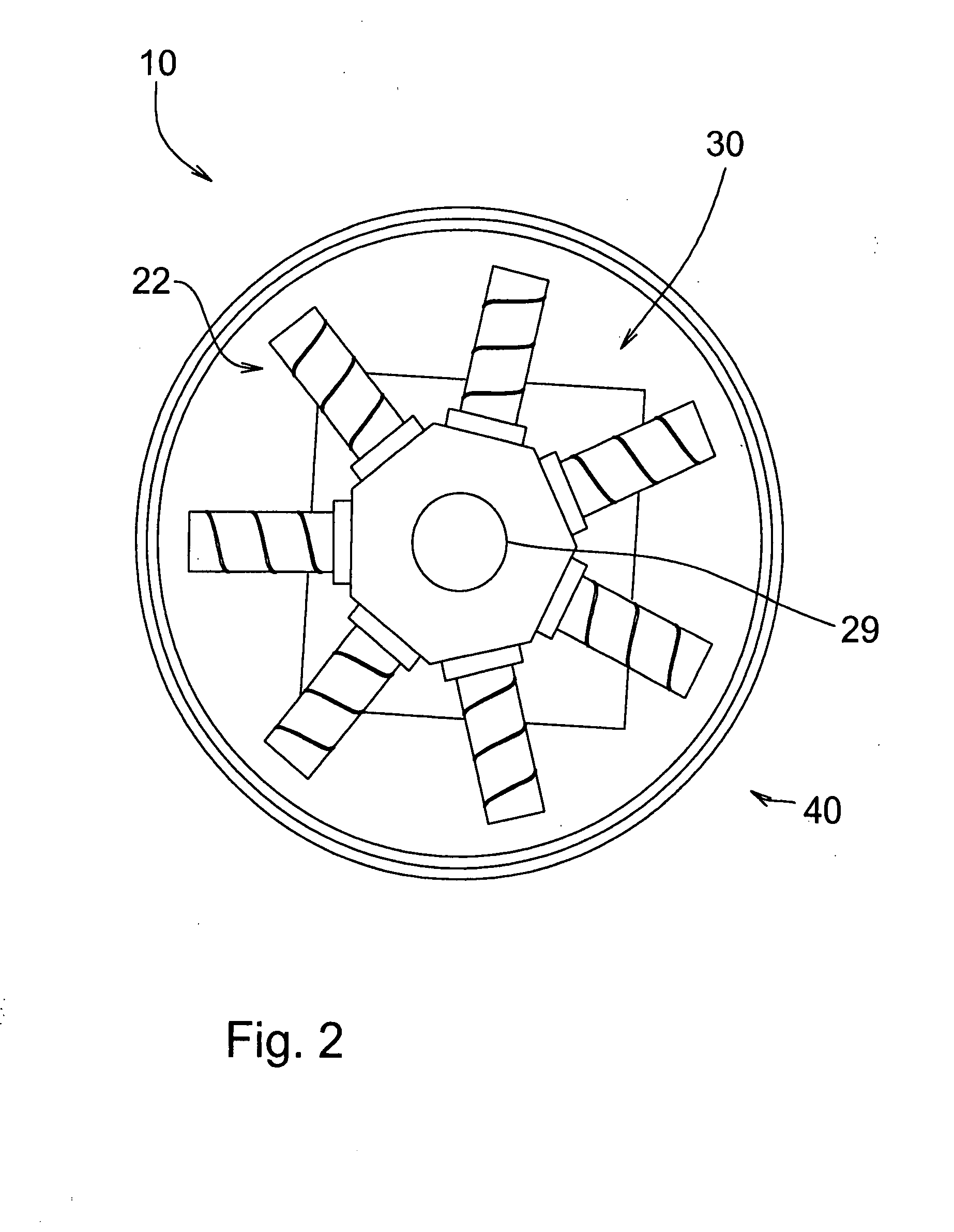
[0022]Referring now to the drawings, wherein similar parts are identified by like reference numerals, FIG. 1 shows a perspective view of the preferred embodiment of the passive tracking antenna system 10. Antenna system 10 includes an antenna array 20 attached to diversity electronics 30. Diversity electronics 30 is attached to a mounting interface 40 having base feet 42. Diversity electronics 30 includes a touch pad 32, a display 34, and mode switches 36 on the front surface thereof. Antenna system 10 may be inflatable to allow for easy transportation. Further, if array 20 is large enough, diversity electronics 30 can be positioned within the center portion of array 20, below upward pointing antenna member 29.

[0023]Array 20 includes antenna sectors 21 each having an upper antenna tube 22 and a lower antenna tube 24 to provide a hardware formed viewing angle and an increase in sector gain without making the entire antenna sector 21 too large. Antenna tubes 22 and 24 each contain a s...


PUM


Abstract

The present invention involves a tracking antenna system with no moving parts that extends the range of wireless mobile links 16 to 256 times the range of regular omni-directional whip antennas. The antenna system comprises an array of antenna segments arranged in a sphere or circle, or other suitable geometry. Each antenna segment includes one or more antennas connected and combined in parallel. Each antenna segment feeds a tuner and subsequent diversity electronics that optimizes both the transmission and reception in order to achieve the best possible range. The antenna system can be used from unmanned air, ground, and surface vehicles to mobile ground stations in motion, as well as between flying planes, moving vehicles, sailing boats, or any combination thereof. The system may be expanded further to many more levels of architecture as required. For example, this system may be expanded to a Level 2 diversity engine combination of any number and type of Level 1 antenna array units depending upon the diversity expansion required and the criteria for Level 2.

Description

[0001]This patent application claims the benefit of earlier filed U.S. provisional patent application Ser. No. 60 / 798,609 filed on May 8, 2006.FIELD OF THE INVENTION[0002]The present invention generally relates to the field of antenna systems. More specifically, this patent relates to passive tracking antenna systems. The term “passive” in this application specifically means that the system has no moving parts present.BACKGROUND OF THE INVENTION[0003]Antenna systems use either an omni antenna to avoid tracking the source or use directional antennas with some means of following or tracking the source. The omni antenna has many disadvantages, for example low gain, which limits the operating range, susceptibility to jamming and interference, etc. Directional antennas on the other hand, require a global positioning system (GPS) to perform tracking or some other form of rotating direction finding equipment. Moving parts have their obvious disadvantages, for example, wear and tear of the ...

Claims


Application Information

Patent Timeline
Patent Type & Authority Applications(United States)
IPC IPC(8): H01Q3/00
CPCH01Q1/362H01Q21/067H01Q21/205H01Q11/08
Inventor WEINSTEIN, ELIAHUEULMI, SAM H.
Owner WEINSTEIN ELIAHU
Why Eureka
Try Eureka