High Performance Three-Port Switch for Managed Ethernet Systems

a technology of managed ethernet and switch, which is applied in the direction of data switching networks, frequency-division multiplexes, instruments, etc., can solve the problems of improper installation of cable terminators, relative short cables, poor connection, etc., and achieve the effect of quick and easy operation

Inactive Publication Date: 2008-07-24
PANDUIT
View PDF99 Cites 32 Cited by
  • Summary
  • Abstract
  • Description
  • Claims
  • Application Information

AI Technical Summary

Benefits of technology

[0008]A method and apparatus are provided for isolating and analyzing segments of a deployed, operational cable plant from a remote location. Individual cables, or segments, within an operationally deployed cable plant infrastructure may be isolated and analyzed without requiring a technician to physically inspect and perform an on-site analysis. The approach allows a cable segment to be isolated and analyzed without physically disconnecting the cable from the deployed infrastructure. By isolating and analyzing selected cable plant segments, an entire deployed cable plant infrastructure may be discretely analyzed and specific problems within the cable plant infrastructure may be identified. The approach allows the analyses to be performed quickly and easily from a remote location. Further, the approach is compatible with and may be integrated within a multipurpose network management system.

Problems solved by technology

One of the difficult challenges faced by Information Technology (IT) infrastructure network managers is determining how to diagnose with specificity network faults that are related to faults in a deployed cable plant infrastructure.
Faults associated with relatively short cables, such as patch panel cords used within network equipment closets, are often related to damaged or improperly installed cable terminators and / or internal cable shorts due to an inadvertent pinching or crushing of the cable.
Poor connections can also be caused by damaged sockets in patch panels and / or network equipment.
Unfortunately, faults associated with longer cable runs, typically associated with the horizontal (or distribution) cable plants, may be even more problematic.
Although cables may perform adequately when first installed, over time, numerous faults may arise.
For example, network connections supported by individual cables may begin to experience difficulties due to corrosion, or due to small nicks / cracks in the conductors (introduced during the installation process and / or introduced during subsequent maintenance) that develop into larger cracks or breaks in conductors.
Further, shorts between wires may arise due to damage to conductors or damage to conductor insulation internal to a cable's protective casing.
Such damage is typically caused by the stress of pulling a cable through conduits and tight locations, chafing of cable casings, melting of wire casings due to wires having been inadvertently placed near hot surfaces such as overhead lighting, damage due to rodents chewing cable casings, and a litany of other potential sources of physical damage.
In addition, interference may be introduced to one or more cables in a cable segment by sources of electromagnetic radiation such as electric motors, electrical boxes, etc.
Unfortunately, such physical inspections take significant time on the part of the technician as the technician attempts to locate both ends of a cable, disconnect the cable from the network, attach test equipment, and proceed to analyze the cable.
Further, such a test does not adequately test the connections between the cable and the cable plant jacks to which the cable connects.
In addition, the process of disturbing a cable may result in the introduction of new problems which may have otherwise been avoided.
The above process is more complicated in large IT networks involving cable plants within multiple physically distributed locations or remote locations.

Method used


Image

  • High Performance Three-Port Switch for Managed Ethernet Systems
  • High Performance Three-Port Switch for Managed Ethernet Systems
  • High Performance Three-Port Switch for Managed Ethernet Systems

Examples


Embodiment Construction

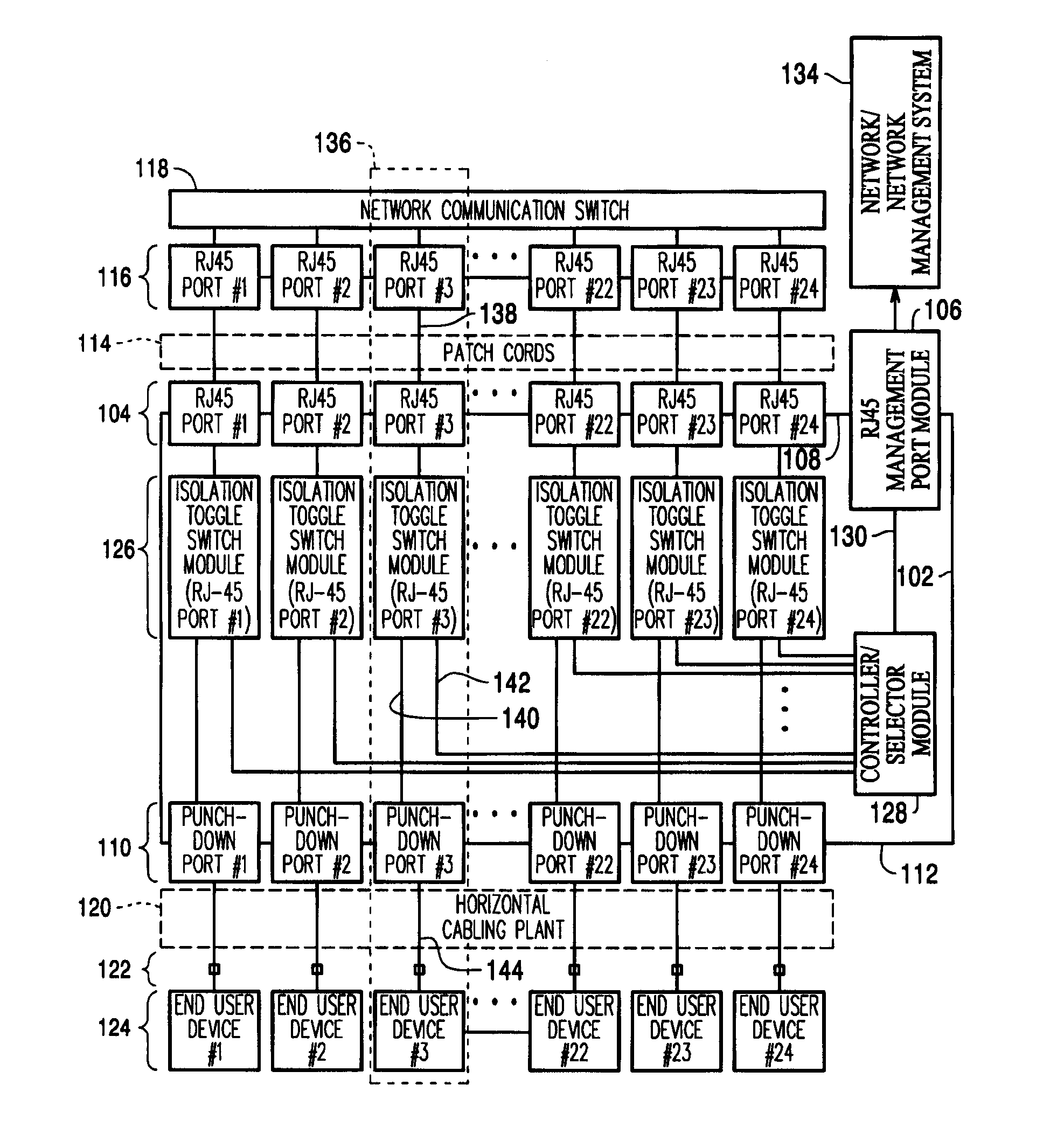
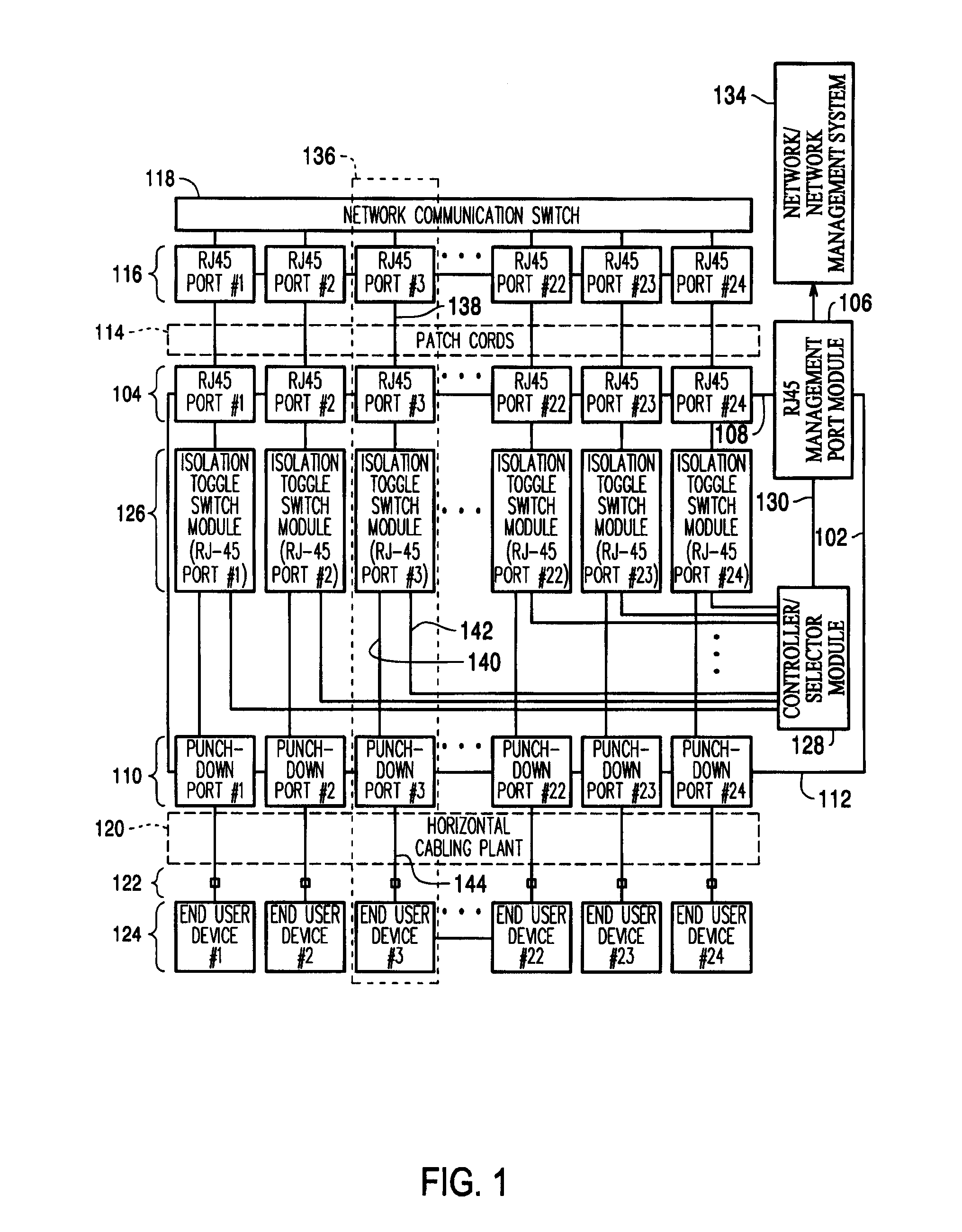
[0020]FIG. 1 is a system-level block diagram of an exemplary patch panel 102 capable of isolating and supporting the analysis of a cable deployed within an operational cable plant. As shown in FIG. 1, patch panel 102 may include a front patch panel face 108 that may include a plurality of RJ-45 patch panel ports 104 and an RJ-45 management port 106. Patch panel 102 may further include a rear patch panel face 112 that may include a plurality of punch-down ports 110. As shown in FIG. 1, each of the plurality of RJ-45 ports 104 on front patch panel face 108 may connect to one of a plurality of ports 116 on a network communication switch 118 via one of a plurality of patch cords 114. As further shown in FIG. 1, each of the plurality of punch-down ports 110 may connect via one of a plurality of cables in horizontal cabling plant 120 to an end-user device jack 122. Each end-user device jack 122 shown in FIG. 1 may support a connection from an end-user network device 124 to a network via n...


PUM


Abstract

A method and apparatus for isolating and analyzing segments of a deployed, operational cable plant from a remote location. Individual cables, or segments, within an operationally deployed cable plant infrastructure may be isolated and analyzed without requiring a technician to physically inspect and perform an on-site analysis. The approach allows a cable segment to be isolated and analyzed without physically disconnecting the cable from the deployed infrastructure. By isolating and analyzing selected cable plant segments, an entire deployed cable plant infrastructure may be discretely analyzed and specific problems within the cable plant infrastructure may be identified. The approach allows the analyses to be performed from a remote location and is compatible with and may be integrated within a multipurpose network management system.

Description

BACKGROUND[0001]1. Technical Field[0002]This invention pertains to network cable infrastructure maintenance. In particular, the present invention pertains to apparatus and techniques for isolating and analyzing operationally deployed segments of a network cable plant infrastructure.[0003]2. Description of Related Art[0004]One of the difficult challenges faced by Information Technology (IT) infrastructure network managers is determining how to diagnose with specificity network faults that are related to faults in a deployed cable plant infrastructure.[0005]Faults associated with relatively short cables, such as patch panel cords used within network equipment closets, are often related to damaged or improperly installed cable terminators and / or internal cable shorts due to an inadvertent pinching or crushing of the cable. Poor connections can also be caused by damaged sockets in patch panels and / or network equipment. Unfortunately, faults associated with longer cable runs, typically a...

Claims


Application Information

Patent Timeline
Patent Type & Authority Applications(United States)
IPC IPC(8): G06F11/00
CPCH04L41/0659H04Q3/0062H04L49/555H04L43/0811
Inventor CAVENEY, JACK E.NORDIN, RONALD A.
Owner PANDUIT
Why Eureka
Try Eureka