Catheter introducer system

Inactive Publication Date: 2008-07-24
HEUSER +1
View PDF80 Cites 56 Cited by
  • Summary
  • Abstract
  • Description
  • Claims
  • Application Information

AI Technical Summary

Benefits of technology

[0009]When the catheter is at a desired location, it may be fixed longitudinally in place and blood loss through the sheath minimized by selective tightening of a hemostasis valve that includes a chuck that radially grips th

Problems solved by technology

This may cause trauma to the derma and blood vessel, or require a second needle insertion if the tip is damaged to the extent it prevents suitable insertion.
However, blood leakage past the washer is sometimes significant, causing unwanted complications to the catheterization proced

Method used


Image

  • Catheter introducer system
  • Catheter introducer system
  • Catheter introducer system

Examples


Embodiment Construction

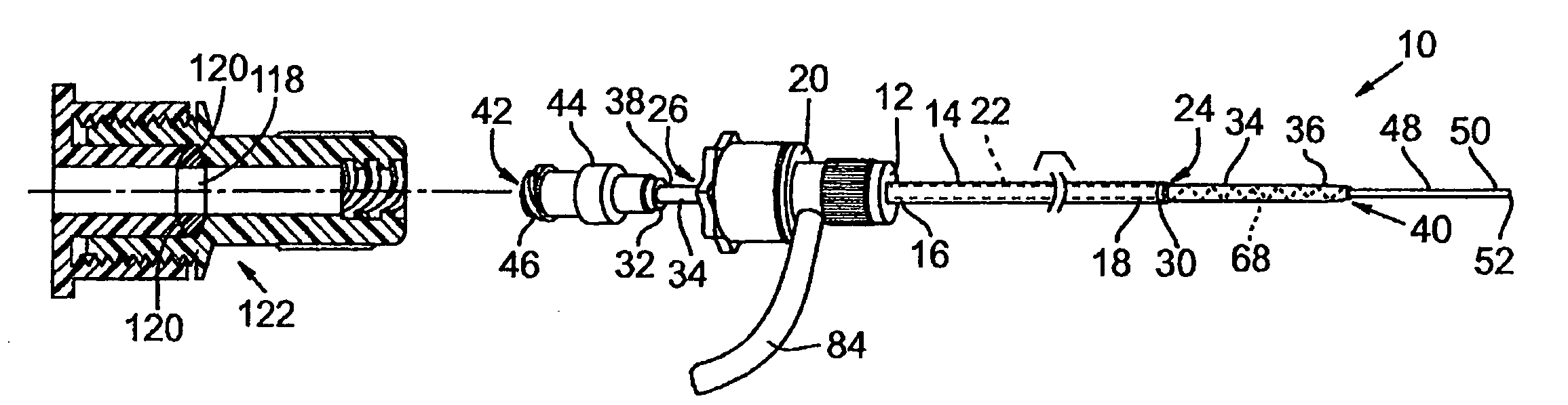
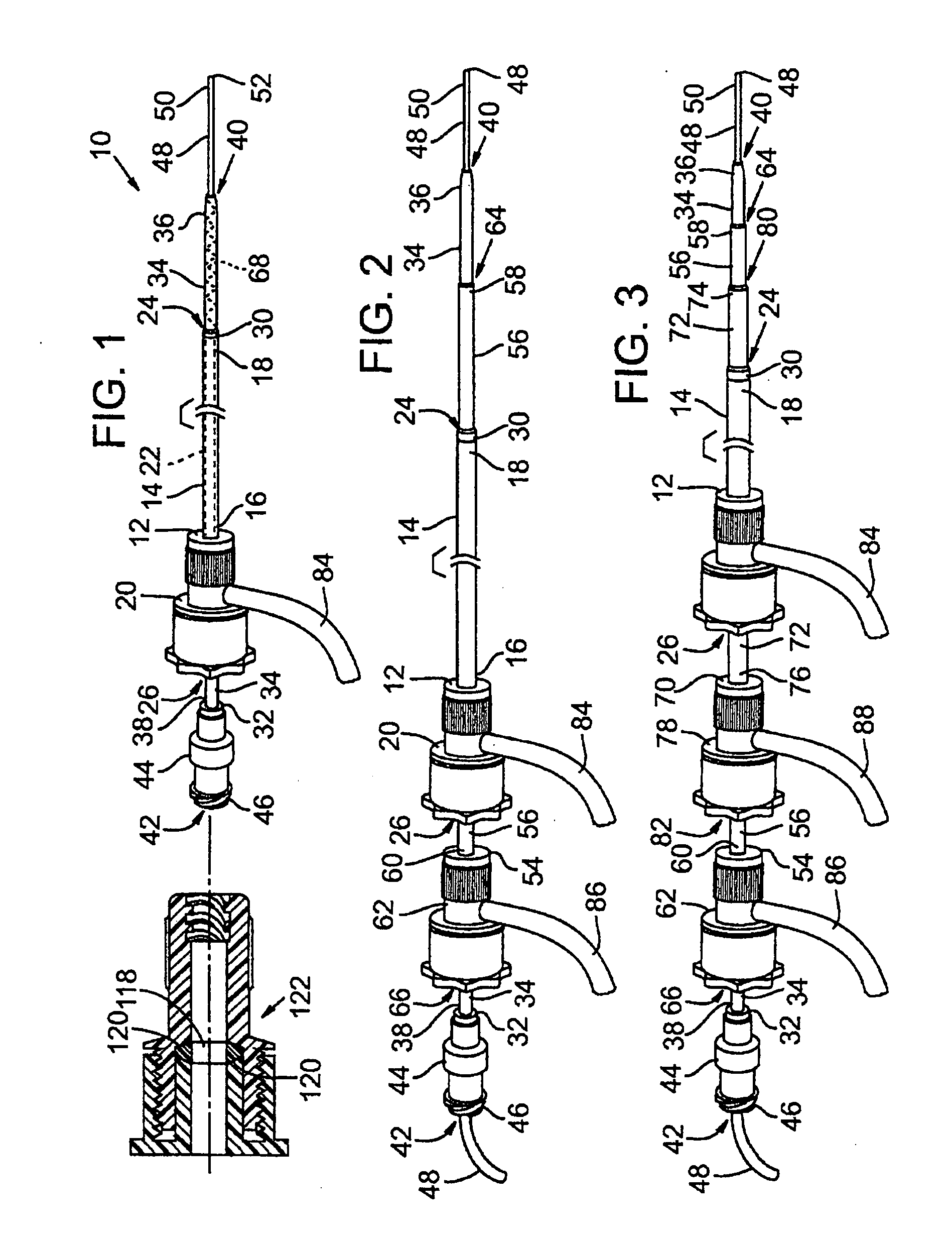
[0033]A catheter introducer system in accordance with the present invention is indicated generally at 10 in FIG. 1. Catheter introducer system 10 includes a sheath 12 having a generally elongate, typically cylindrical body 14 with a proximal end 16 and a distal end 18. Body 14 of sheath 12 is coupled at proximal end 16 to a housing 20. A central, typically cylindrical lumen 22 is defined within sheath 12 extending out through a distal opening 24 and a proximal opening 26. Sheath 12 is thus configured to receive a catheter 28 (FIG. 5) for longitudinal movement through and torsional movement within lumen 22.

[0034]Body 14 of sheath 12, is typically composed substantially of a flexible material, such as a plastic, polymeric material, preferably a hydrophilic material. Body 14 may include a reinforcement, such as stainless steel ring 30, to prevent buckling or crimping of distal end 18 at opening 24 when sheath 12 is inserted into a human blood vessel. The stainless steel ring 30 on the ...


PUM


Abstract

Disclosed is an improved pointed instrument for insertion into blood vessels where an occlusion arises or terminates too closely to the insertion site for proper sheath placement. The pointed instrument exhibits supportive characteristics that allow for a sheath to be placed in an otherwise inaccessible insertion site. One embodiment of the present disclosure features a pointed instrument having a flexible portion, which is generally straight outside the body, but agglomerates once inside a blood vessel.

Description

CROSS REFERENCE TO RELATED APPLICATIONS[0001]This application is a continuation-in-part of U.S. patent application Ser. No. 11 / 656,898, filed on Jan. 22, 2007, by Applicant Richard Heuser, the disclosure of which is incorporated by reference. This application also claims priority to Provisional Application Ser. No. 60 / 887,277, filed on Jan. 30, 2007, the disclosure of which is incorporated by reference.BACKGROUND[0002]Catheters typically are inserted into a blood vessel through a sheath which is fixed in place relative to the blood vessel. The sheath protects the vessel and adjacent derma around the point of insertion while the catheter is advanced and withdrawn as necessary for the particular treatment being applied. The sheath is prepared for insertion by first placing a dilator within the lumen of the sheath and a needle or pointed wire within the lumen of the dilator. The needle or wire is used to pierce the derma and the blood vessel's wall and then is advanced into the blood v...

Claims


Application Information

Patent Timeline
IPC IPC(8): A61M25/01
CPCA61B17/3415A61B17/3462A61B17/3498A61B2017/00867A61M25/0662A61M2039/0633A61M39/0613A61M2025/0004A61M2025/0681A61M2025/0687A61M29/00
Inventor HEUSER, RICHARD R.JOYE, JAMES D.
Owner HEUSER
Why Eureka
Try Eureka