System, device, and method for providing access in a cardiovascular environment

a cardiovascular environment and access technology, applied in the field of cardiovascular and vascular surgery, can solve the problems of inferior valvotomy or commissuromy, pose certain problems for surgeons, other bodily injuries, etc., and achieve the effects of enhancing the effect of the operation, superior control, management and performance, and high precision

Inactive Publication Date: 2006-08-10
CASTLEWOOD MEDICAL TECH
View PDF4 Cites 36 Cited by
  • Summary
  • Abstract
  • Description
  • Claims
  • Application Information

AI Technical Summary

Benefits of technology

[0009] From the foregoing, it may be appreciated by those skilled in the art that a need has arisen for an improved instrument for achieving superior control, management, and performance during a procedure that offers optimal access at a targeted surgical site. In accordance with an embodiment of the present invention, a device, a system, and a method for enhancing an operation involving access (particularly, but not limited to, left ventricular access) are provided that includes a flexible, highly precise, easy-to-use device, which substantially eliminates or greatly reduces disadvantages and problems associated with conventional equipment and instruments.
[0012] Certain embodiments of the present invention may provide a number of technical advantages. For example, the present system can include a simple locking mechanism for maintaining a position of the device. The locking mechanism allows a surgeon to unhand the device and, thereby, offers exceptional flexibility and adaptability for a surgeon. Moreover, the operation of the device allows the port to be “dropped” back into the chest (i.e. not directly handled by the operator), while another device or tool is being readied for use. Still other advantages of the device would include minimizing blood loss during intra-ventricular surgical repair, while maintaining a pathway to minimize time during tool changes. The device allows for a number of beating heart surgeries to occur and, further, avoids the complications associated with heart-lung machines.
[0013] In addition, the present invention offers increased accuracy for a surgeon, who is relegated the difficult task of making a precise circular incision in the wall of the heart. Additionally, the device can access and seal a variety of ventricular or cardiac tissue walls.

Problems solved by technology

This surgical technique has proven useful in cases of congenital or acquired supravalvular, valvular, and subvalvular stenoses where more conventional approaches (such as aortic valvotomy or commissurotomy) produce inferior results due to the severity of the obstruction.
These substandard results may also be attributable to difficulties in affecting an accurate obstruction relief, or due to dropping debris from the attended valve (or other similar component).
The debris can readily create an embolus that is free to travel with the blood blow and, potentially, cause a stroke (in the case of lodging in the brain) or other bodily injuries.
Note that such cardiac procedures pose certain problems for a surgeon.
For example, a surgeon is generally confined or restricted in his movements during the surgery, which may be due, in part, to instrumental limitations.
Moreover, many surgical instruments that address issues at the apex of the heart are cumbersome, difficult to manipulate, potentially harmful to patients, and clumsy or awkward in many situations.
Their deficiencies create a significant challenge for the surgeon, who is already being taxed by a number of arduous tasks.
In addition, many current devices are unacceptable because they cause trauma and inflammation issues for the patient or because they have a propensity to cause strokes.
Accordingly, the ability to provide an effective medical instrument that properly accounts for the aforementioned problems presents a significant challenge for component manufactures, system designers, and surgeons alike.

Method used


Image

  • System, device, and method for providing access in a cardiovascular environment
  • System, device, and method for providing access in a cardiovascular environment
  • System, device, and method for providing access in a cardiovascular environment

Examples


Embodiment Construction

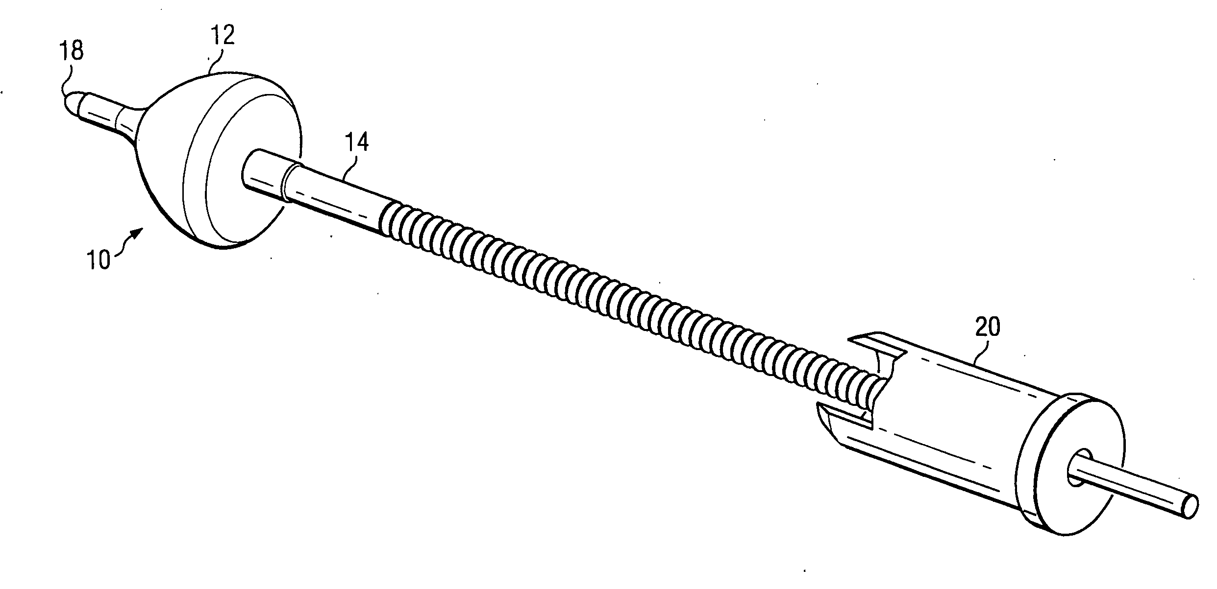
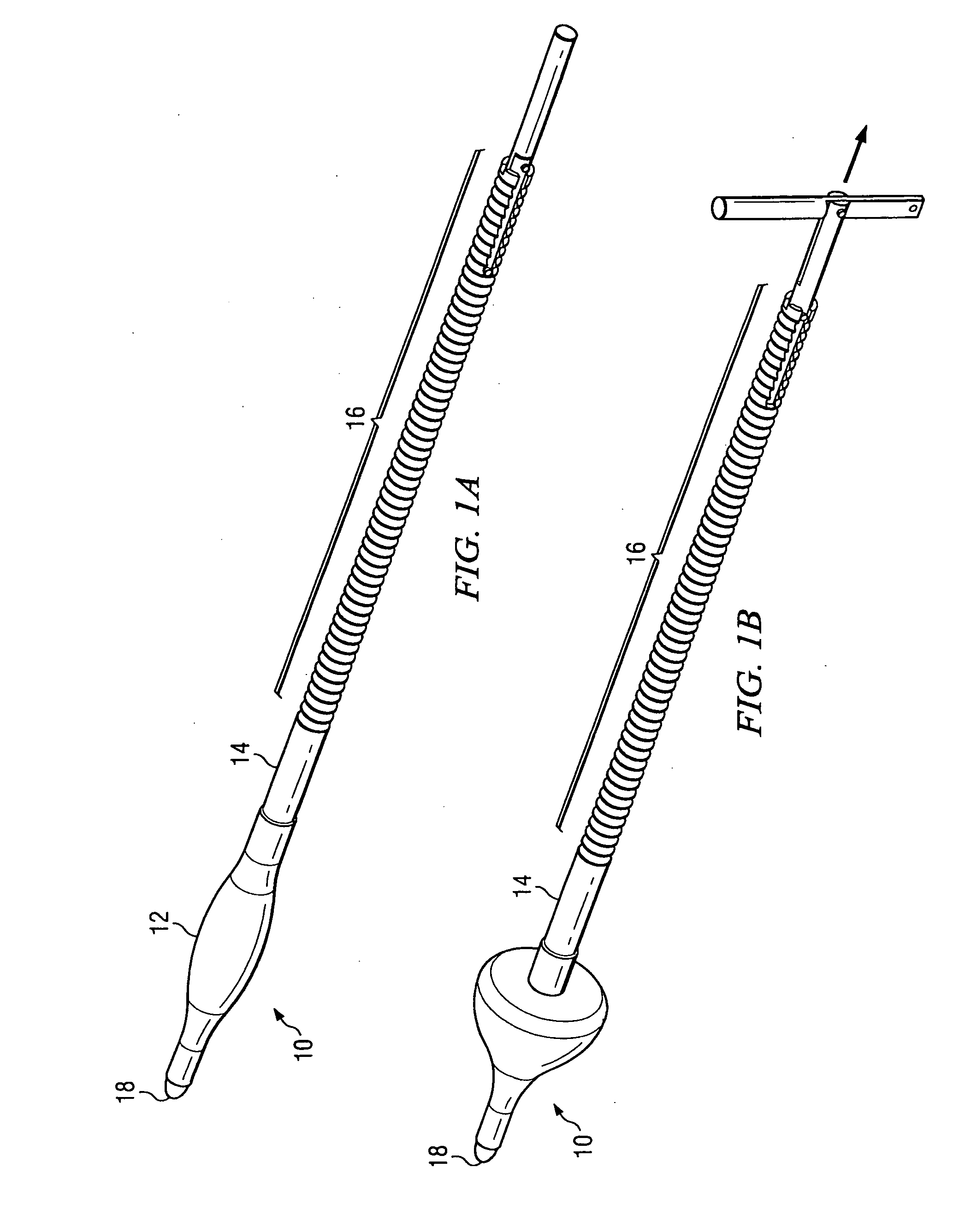
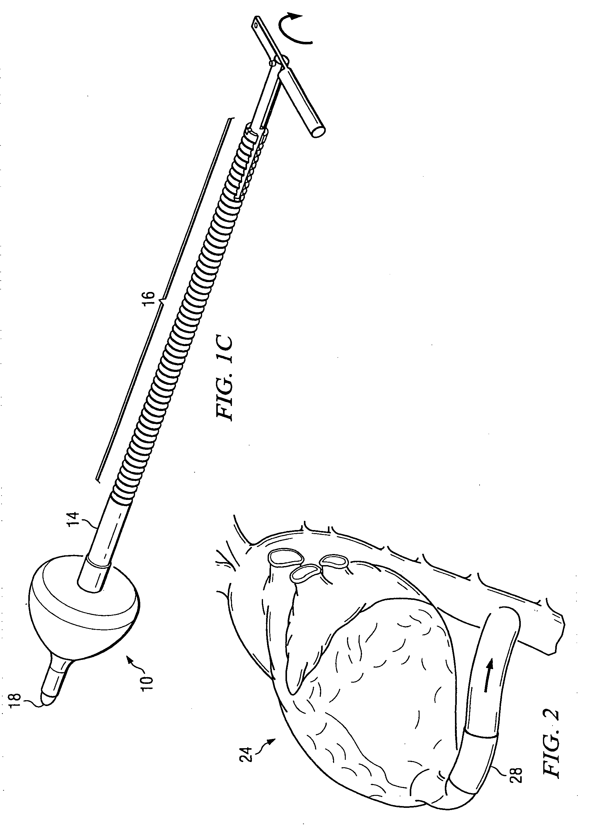
[0022]FIGS. 1A, 1B, and 1C are simplified schematic diagrams that illustrate a device 10 for creating an effective point of entry at a targeted location. In one embodiment, the targeted location is the apex of the heart. However, the targeted location can be any other suitable location in the body in which a small piece of tissue is sought to be removed by a surgeon or where a sealed access to a fluid or gas containing organ is desired. Device 10 includes an expandable element 12 (which is umbrella shaped in one embodiment) and a rod 14, which includes a threaded portion 16. Device 10 also includes an obturator 18, which is olive shaped and which facilitates a smooth streamlined entry for the attending surgeon. In one embodiment, obturator 18 is blunt at its end such that it does not pierce a valve (or other delicate structure) that may be subsequently placed, removed, burned, ablated, or manipulated by the surgeon. Obturator 18 does have enough sharpness or rigidity such that it ac...


PUM


Abstract

A device to be used in a cardiovascular environment, comprising an expandable element that is coupled to a rod and that includes a compressed state and an expanded state. The expandable element is operable to be positioned within a wall of an organ while the expandable element is in the compressed state. The expandable element is further operable to be deployed once it is within the organ such that it is in the expanded state. The device further includes a cutter element operable to make a circular incision at the wall of the organ. The expandable element creates a resistive force when it is pulled against the wall while in the expanded state such that an interface is created for making the incision. The device includes a stop-grip mechanism that maintains the resistive force at the interface. One embodiment features the expandable element being umbrella shaped.

Description

RELATED APPLICATIONS [0001] This Application claims the benefit under 35 U.S.C. § 119(e) of U.S. Provisional Application Ser. No. 60 / 651,690 entitled: “Devices for Accessing Interior Chamber of the Heart and Device for Aiding Construction of Valved Conduits from the Heart,” which was filed on Feb. 10, 2005, and which is incorporated by reference herein.TECHNICAL FIELD OF THE INVENTION [0002] This invention relates in general to the field of cardiac and vascular surgery and, more particularly, to a system, a device, and a method for providing for access in a cardiovascular environment. BACKGROUND OF THE INVENTION [0003] The treatment of vascular diseases has grown exponentially in terms of sophistication and diversity. One area of interest relates to the ability to access the inside of the heart in order to touch, cut, move, paint, or burn areas of the heart in order to change its function, shape, conduction pattern, or to ablate a normal or an abnormal rhythm pattern. [0004] Another...

Claims


Application Information

Patent Timeline
Patent Type & Authority Applications(United States)
IPC IPC(8): A61F11/00
CPCA61B17/32053A61B17/34A61B17/3421A61B2017/3486A61B2017/3488
Inventor HAMMAN, BARON L.
Owner CASTLEWOOD MEDICAL TECH
Why Eureka
Try Eureka