
Transfacet-Pedicle Locking Screw Fixation of Lumbar Motion Segment

a technology of lumbar motion segment and locking screw, which is applied in the field of spinal apparatus and methods, can solve the problems of significant surgical trauma, clinically significant hardware impingement on soft tissues, and inherent inability of the construct to withstand the physiological torque experienced by the lumbar motion segment, so as to reduce the risk of injury, the effect of reducing the risk of muscle irritation and reducing the risk of invasiveness

Inactive Publication Date: 2009-04-09
OSMAN SAID G
View PDF3 Cites 32 Cited by
  • Summary
  • Abstract
  • Description
  • Claims
  • Application Information

AI Technical Summary

Benefits of technology

[0005]The transfacet-pedicle locking screw fixation device and method of the invention overcomes the drawbacks of the prior art and achieves marked improvement over the prior art. In particular, the invention provides the least invasive of all current lumbar spine fixation devices since only the pair of facet joint and only the pair of pedicles (of the same vertebra) are instrumented, hence reducing the risk of injury to the cephalad facet joint (as is the case with pedicle screw instrumentation) by 100%. Since the fixation is entirely intra-osseous and transfacet, there is minimal risk for muscle irritation. Moreover, there is hardly any recordable blood loss since the procedure is entirely percutaneous. Additionally, due to less hardware implantation required and minimal wound closure, the operative time is significantly reduced.
[0006]The assembly of the described embodiments combines the positive attributes of the pedicle screws and transfacet fixation, that is, minimal surgical trauma and a strong reliable fixation. It markedly reduces the patient's need for pain medication, and it markedly reduces patient down time. Combined with the technique of least invasive interbody fusion, it will provide a 360 degree spinal fusion whose stability will challenge any construct currently available for clinical use, while maintaining the least surgical trauma and minimal blood loss.

Problems solved by technology

Even with so-called minimally invasive pedicle screw fixation, there is significant surgical trauma, and clinically significant hardware impingement on soft tissues since the locations of the screw heads and the rods are inter / intramuscular.
The problem with the prior facet fixation, however, is the inherent inability of the construct to withstand the physiological torque experienced by the lumbar motion segments.

Method used


Image

  • Transfacet-Pedicle Locking Screw Fixation of Lumbar Motion Segment
  • Transfacet-Pedicle Locking Screw Fixation of Lumbar Motion Segment
  • Transfacet-Pedicle Locking Screw Fixation of Lumbar Motion Segment

Examples


Embodiment Construction

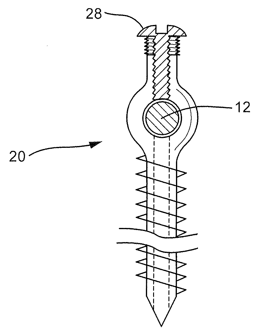
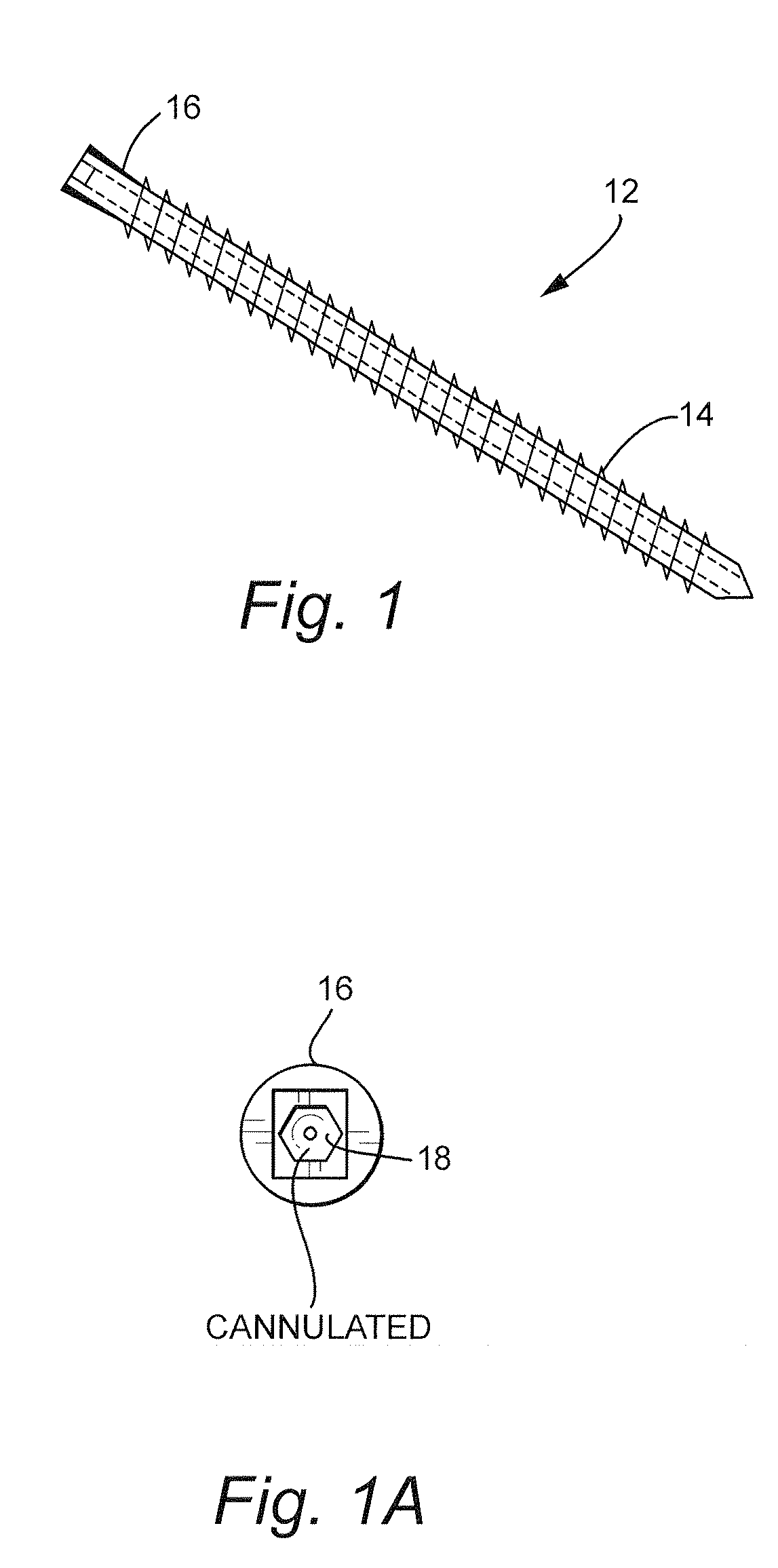
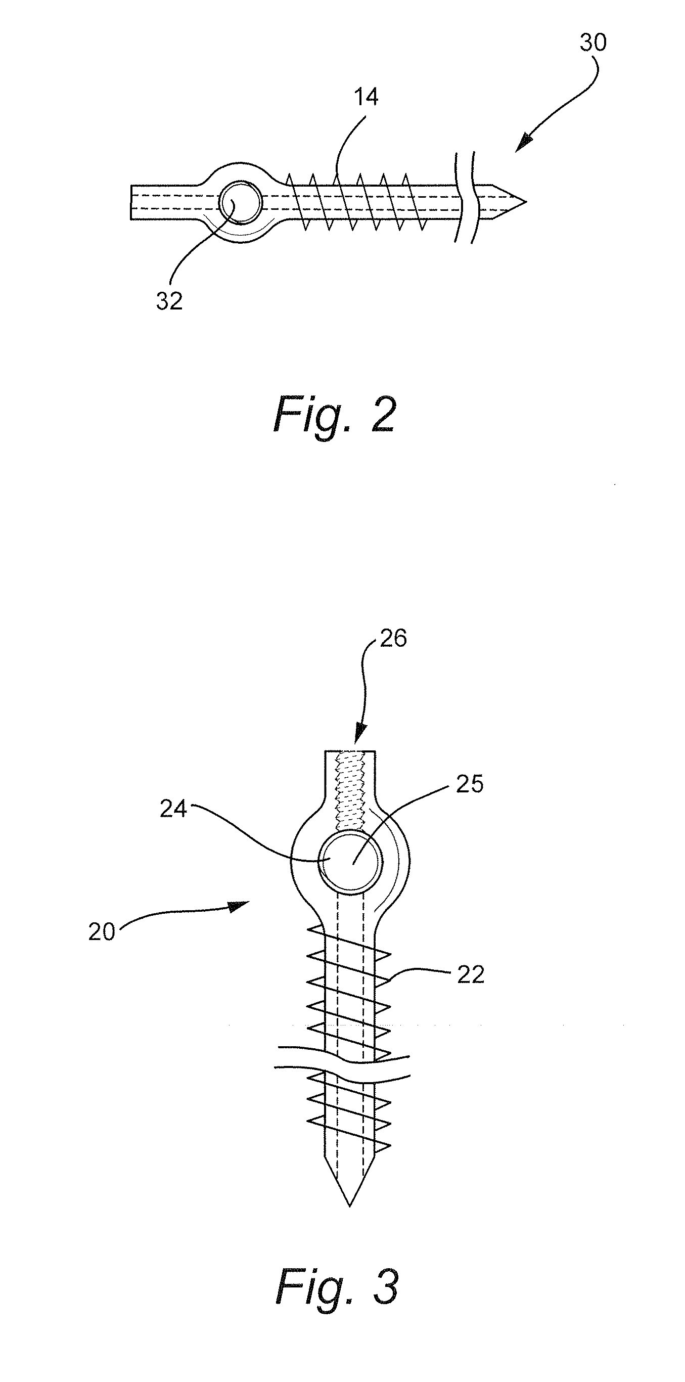
[0024]With reference to the drawings, a transfacet-pedicle locking screw fixation assembly includes a plurality of components that provide for spine fixation using only one pair of facet joints and only one pair of pedicles (of the same vertebra), thereby reducing the risk of injury to the cephalad facet joint. The assembly includes a first male transfacet locking screw 12 including threads 14 at least at a distal end. Preferably, the locking screw 12 is fully threaded and cannulated. The locking screw 12 can be made of a metal alloy, a bioabsorbable material, or a bio-incorporable material or other suitable material of variable lengths and diameters. The length of the screw 12 varies according to the patient's anatomy. As shown in FIG. 1A, the screw head 16 includes a shaped socket 18 that is shaped to receive a suitable screw driver (discussed in more detail below). As shown, the socket 18 is preferably hexagonal shaped, although other shapes may be suitable.

[0025]With reference t...


PUM


Abstract

A transfacet-pedicle locking screw fixation assembly includes a plurality of pedicle screws each including threads at a distal end and a connecting receptacle at a proximal end. The connecting receptacle is oriented perpendicularly with respect to a longitudinal axis of the pedicle screw. A basic transfacet locking screw including threads at least at a distal end has the distal end engaging the connecting receptacle in one of the pedicle screws. The transfacet locking screw may also be interlocked with another transfacet locking screw.

Description

CROSS-REFERENCES TO RELATED APPLICATIONS[0001]This application claims the benefit of U.S. Provisional Patent Application Ser. No. 60 / 978,596, filed Oct. 9, 2007, the entire content of which is herein incorporated by reference.STATEMENT REGARDING FEDERALLY SPONSORED RESEARCH OR DEVELOPMENT[0002](NOT APPLICABLE)BACKGROUND OF THE INVENTION[0003]The invention relates to apparatus and methods for spinal fixation and, more particularly, to a transfacet-pedicle locking screw fixation device and method of insertion for stabilizing a facet joint and an adjacent target pedicle.[0004]Instrumented spinal fixation is in common practice. Pedicle screw fixation requires instrumentation of the pedicles on either side of the target disc. Even with so-called minimally invasive pedicle screw fixation, there is significant surgical trauma, and clinically significant hardware impingement on soft tissues since the locations of the screw heads and the rods are inter / intramuscular. Less invasive and less b...

Claims


Application Information

Patent Timeline
IPC IPC(8): A61B17/04
CPCA61B17/7064A61B17/8897A61B17/888A61B17/864
Inventor OSMAN, SAID G.
Owner OSMAN SAID G
Learn More