Bloodless treating apparatus

a treatment apparatus and bloodless technology, applied in the direction of suction devices, other blood circulation devices, medical devices, etc., can solve the problems of failure of treatment, inability to avoid bleeding, and reduce the pressure of patients, so as to reduce the amount of bleeding, the effect of substantially reducing the amount of bleeding

Inactive Publication Date: 2005-02-15
TOMIO OHTA +1
View PDF25 Cites 40 Cited by
  • Summary
  • Abstract
  • Description
  • Claims
  • Application Information

AI Technical Summary

Benefits of technology

In the case in which the object is injured to bleed in a considerable amount when the surgical treatment is applied to the object upon an ordinary operation (without using the apparatus of the present invention), when the apparatus of the present invention is used, the fluid replacement is supplied to the object and the fluid replacement existing in the object is mainly discharged whether or not the blood is recovered which is contained in the fluid replacement, so that the bleeding amount is substantially reduced. That is, even in the case of injuring the object, the fluid replacement flows out in place of the blood so that the bleeding amount is substantially reduced when the apparatus of the present invention is used, and thereby the problems involved in the bleeding as described above can be avoided or alleviated.
It is noted that the term of “bloodless” which is used in the present invention does not mean completely no bleeding but means a substantially less bleeding amount upon applying the surgical treatment to the objet by means of the apparatus of the present invention compared with the conventional surgical treatment, thereby the problems in the prior art as described above are substantially avoided or substantially alleviated. Of course, the substantial amount of the bleeding is minimized in the most preferred embodiment.

Problems solved by technology

Upon applying such a surgical treatment, it is of course desirable to reduce a bleeding amount as small as possible, but the bleeding can not be avoided.
The large bleeding amount results in a problem of a viewing field in that the object to which the surgical treatment is applied is blinded due to the bleeding blood, and such problem may leads to a failure of the treatment.
Additionally, a blood pressure of a patient may be lowered due to the large bleeding amount so that there is a possibility that the treatment itself can not be continued.
The above blood recovery requires an expensive disposable device and an expensive apparatus, so that it cannot be applied to any surgical treatment.

Method used


Image

  • Bloodless treating apparatus
  • Bloodless treating apparatus
  • Bloodless treating apparatus

Examples


case 1

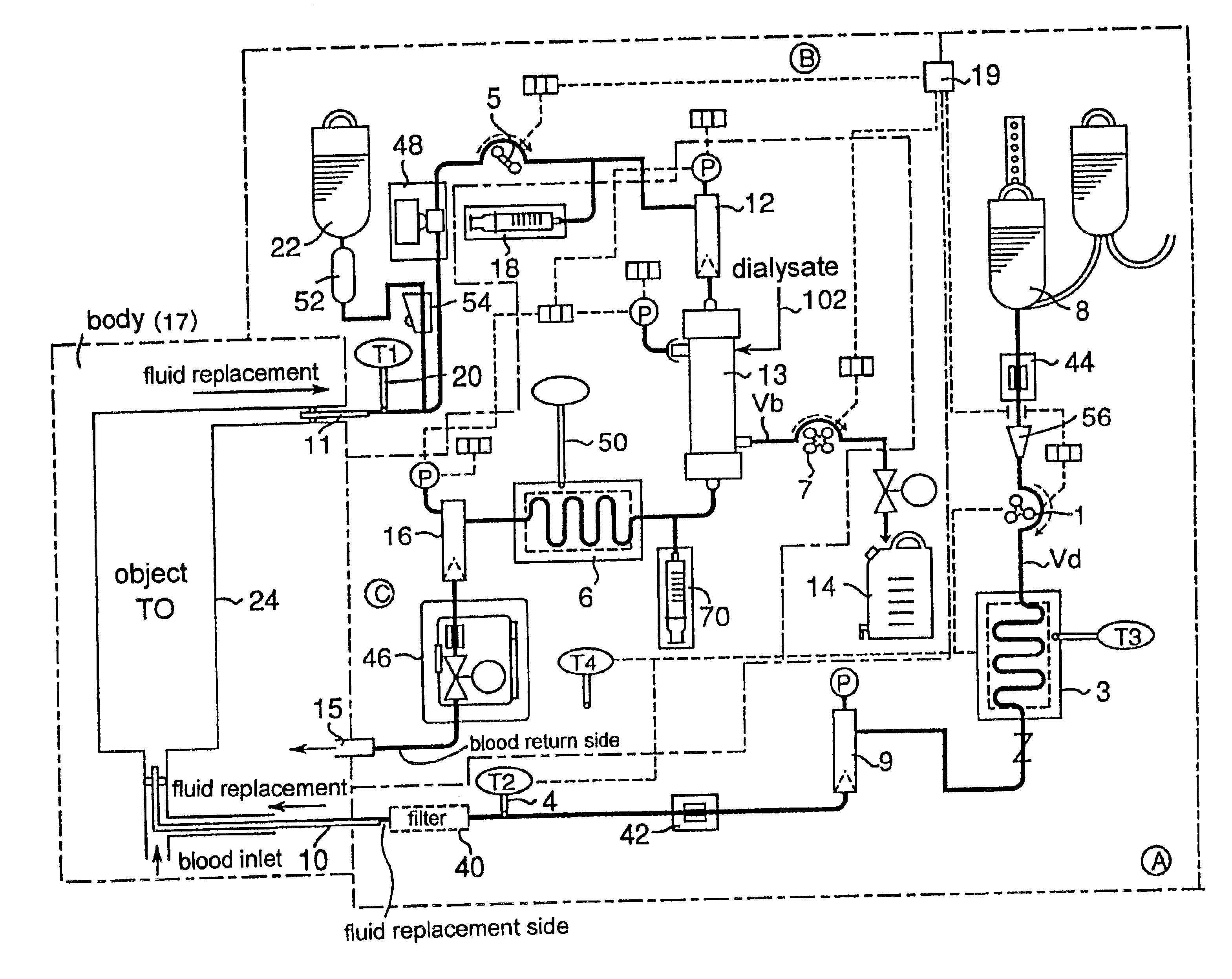
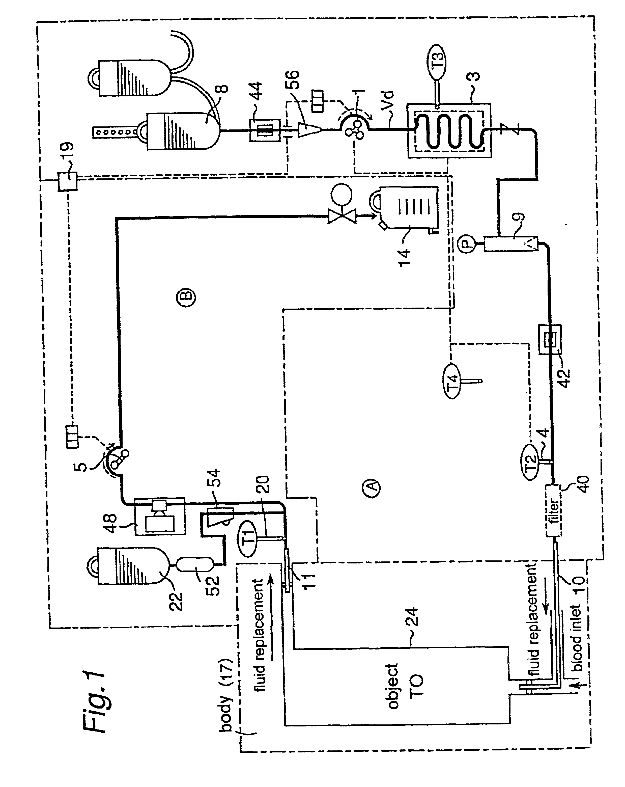
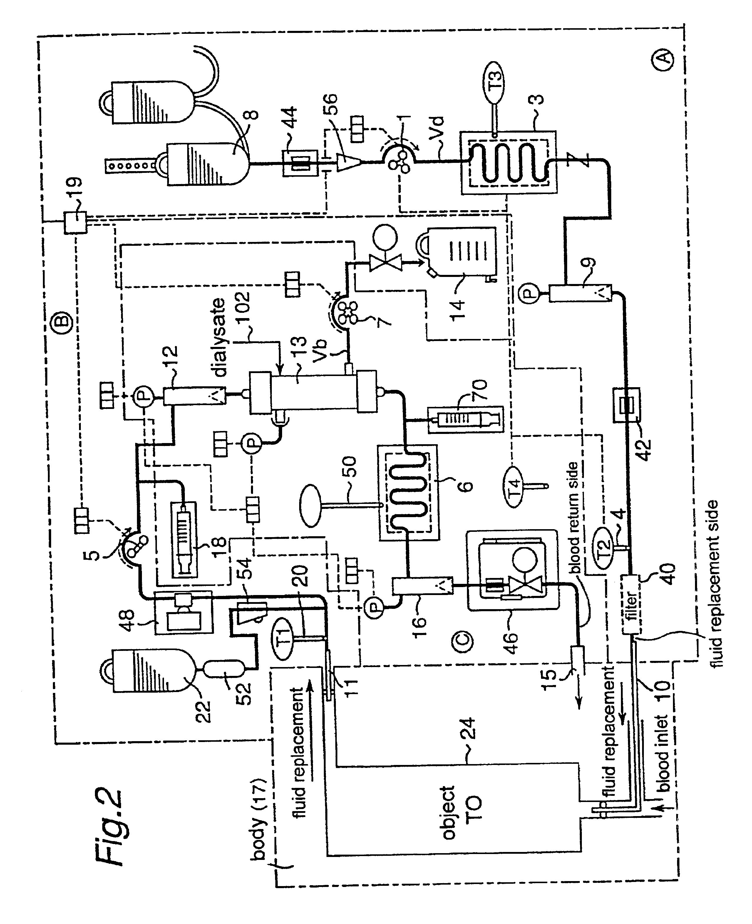
Fluid replacement is charged beforehand from a fluid replacement bottle (22) into the elements and the conduits in the apparatus. First, a predetermined temperature (T0) to which the object is controlled and operation conditions such as a supplied fluid replacement rate, a withdrawn fluid replacement rate and so on are determined depending on an object (24) to which the surgical treatment is applied and the treatment for the object. Then, a heat exchanger (3) is operated, and its adjusting temperature (T3) is set at for example the predetermined temperature (T0). Upon this, the adjusting temperature (T3) may be shifted a little from the predetermined temperature (T0) considering the heat absorption or heat loss after leaving the heat exchanger (3) until entering the body (namely, ΔT) as well as the temperature change after entering the body until reaching the object.

Each catheter is inserted into the blood vessel, and the pump (1) is operated and the fluid replacement is supplied fr...

case 2

Although in Case 1, only the withdrawn fluid replacement temperature (T1) is taken into account, the supplied fluid replacement temperature (T2) is also considered in addition to the withdrawn fluid replacement temperature (T1) in Case 2. In this case, the averaged temperature Tav of T1 and T2 (=(T1+T2) / 2) may be regarded to indicate the actual temperature of the object (T0), and this case is generally superior in the estimation of the object temperature to Case 1 wherein only T1 is considered. Similarly to Case 1 described above, the different extent between the averaged temperature (Tav) and the predetermined temperature of the object region (T0), for example the difference ΔTb (=(T1−T2) / 2−T0) is obtained. The others are substantially the same as those in Case 1. It is noted that T1 and T2 have the same weight in this case so as to obtain the averaged value, but it may be possible optionally to change their weights. For example, it is possible to use 1.5×T1 in place of T1, and 0.5...

case 3

Temperature adjustment of the heat exchanger (3) may be carried out in various appropriate manners depending on the different extent, for example the value of the difference ΔTa or ΔTb.

For example, when the difference ΔTa is positive in Case 1, the set temperature of the heat exchanger (3) is operated to be lowered so that the withdrawn fluid replacement temperature (T1) is decreased. When the difference ΔTa is negative, the opposite operation is carried out. Upon these operations, it is preferable to consider a static characteristic and / or a dynamic characteristic of the difference ΔTa.

For example, when the difference ΔTb is positive in Case 2, the set temperature of the heat exchanger (3) is operated to be lowered so that the supplied fluid replacement temperature (T2) is decreased. Upon this operation, considering that the difference ΔTb desirably becomes zero, T2 is calculated from the predetermined temperature (T0) and the measured withdrawn fluid replacement temperature throug...


PUM


Abstract

There is provided an apparatus which reduces a bleeding amount upon an operation.
A bloodless treating apparatus used upon a surgical treatment of an objet comprises:
    • (A) a fluid replacement supply unit which quantitatively supplies a fluid replacement into a blood vessel leading to the object (24); and
    • (B) a fluid replacement withdrawing unit which quantitatively withdraws the fluid replacement having passed through the object (24) from a blood vessel coming from the object.

Description

TECHNICAL FIELDThe present invention relates to an apparatus for minimizing a bleeding amount which apparatus is used upon applying a surgical treatment to an object such as an organ, for example an operation, a treatment using an artificial lung or the like in the medical field related to a mammal and especially a human. Hereinafter, such apparatus is also referred to as a “bloodless treating apparatus”.BACKGROUND ARTA surgical treatment such as an operation is applied to an object as a part of a body for various purposes. Upon applying such a surgical treatment, it is of course desirable to reduce a bleeding amount as small as possible, but the bleeding can not be avoided. For example, in the case in which a bleeding amount is large, transfusion with an autologous blood or other's blood is necessary. The large bleeding amount results in a problem of a viewing field in that the object to which the surgical treatment is applied is blinded due to the bleeding blood, and such problem ...

Claims


Application Information

Patent Timeline
Patent Type & Authority Patents(United States)
IPC IPC(8): A61M1/36
CPCA61M1/3621A61M1/3623
Inventor OHTAMIYATAKE, TETSUYAKINOSHITA, YOSHIHIKO
Owner TOMIO OHTA
Why Eureka
Try Eureka