
Snow melting system and method with direct-contact water heater

a technology of direct contact and water heater, which is applied in the direction of fluid heater, lighting and heating apparatus, ways, etc., can solve the problems of low fuel efficiency of devices, inability to achieve high melting rate per unit of fuel consumed or electricity used, and high operating costs, etc., and achieve high efficiency

Inactive Publication Date: 2008-07-31
DAVIES TREVOR
View PDF17 Cites 14 Cited by
  • Summary
  • Abstract
  • Description
  • Claims
  • Application Information

AI Technical Summary

Benefits of technology

[0007]It is a feature of the present invention to provide a compact snow melting system and method which uses a high efficiency direct-contact water heater to produce hot water and wherein the hot water is injected, at a substantially constant pressure, into the snow contained in a snow melting housing.
[0008]Another feature of the present invention is to provide a snow melting system and method wherein hot water is injected by water nozzles directly into the snow thereby causing very little fog or vapour released from the snow.
[0010]Another feature of the present invention is to provide a snow melting system and method wherein substantially all unwanted debris is filtered from the snow and wherein the system can perform at close to 100 percent efficiency.

Problems solved by technology

However, such known devices lack in fuel efficiency and cannot achieve high melting rates per unit of fuel consumed or electricity used.
They are therefore expensive to operate.
Some of these devices are also very bulky and troublesome and require excessive maintenance to defrost the unit during cold weather periods when these units are not in use.
The stacked snow results in an inefficient use of space resulting in the narrowing of streets, a decrease in vacant parking spaces which can be hazardous as it decreases visibility.
Also, parking spaces which use parking meters cannot be employed while large snow banks may be left in place for several days.
The transport of the snow is also expensive.
A disadvantage of these known systems is that they produce fog which causes ice to build up in the vicinity of the systems and this has also proven to be hazardous and can also affect the proper operation of the snow melting apparatus in that ice can build up around valves preventing the operation thereof.
This system poses several disadvantages in that snow can pass around the screen and into the trough and often debris can be found in the trough.
The snow can also clog the exit port of the trough, particularly if debris is directed thereto, such as paper, cardboard and the like clogging material.
Another disadvantage of this apparatus is that the waterlines leading to the water jets can freeze if the device is left outside and not used.
The pivoting screen is also a troublesome design and can also freeze up.
This type of open-ended device also produces an excess quantity of fog in the immediate area thereof particularly when the hot water is sprayed over the snow.
The fog causes the ground to ice-up, making it hazardous to the snow loading equipment and nearby traffic.

Method used


Image

  • Snow melting system and method with direct-contact water heater
  • Snow melting system and method with direct-contact water heater
  • Snow melting system and method with direct-contact water heater

Examples


Embodiment Construction

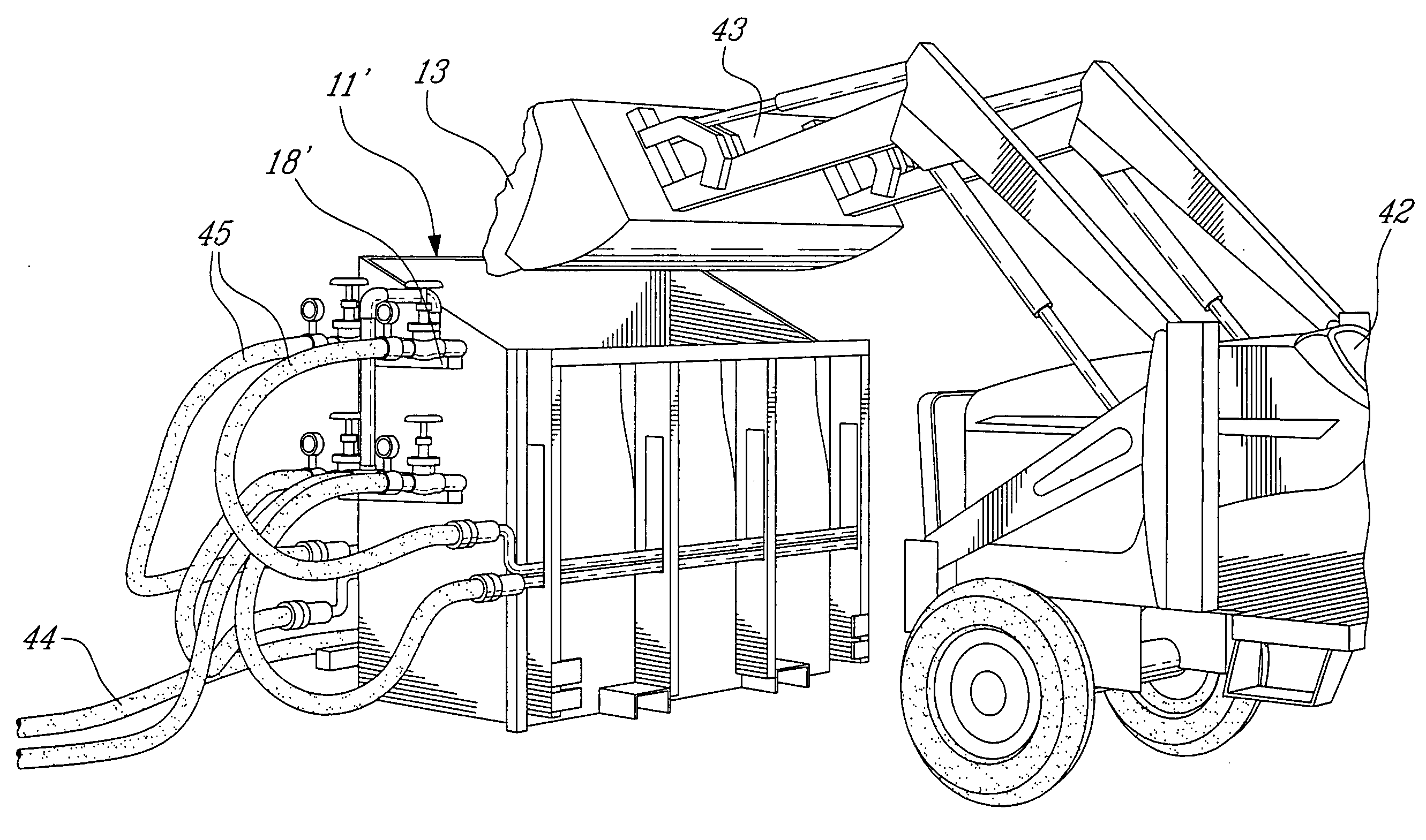
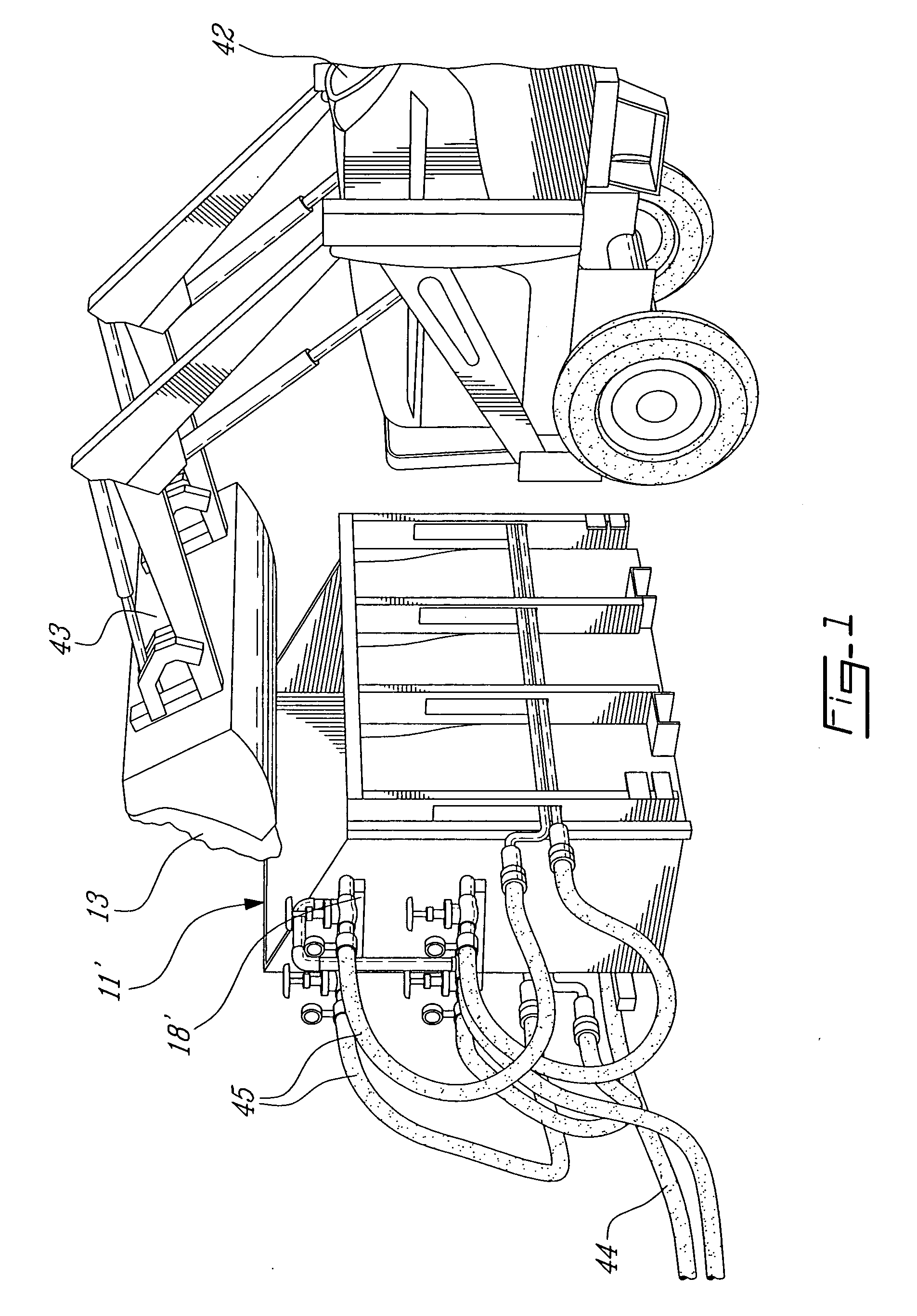
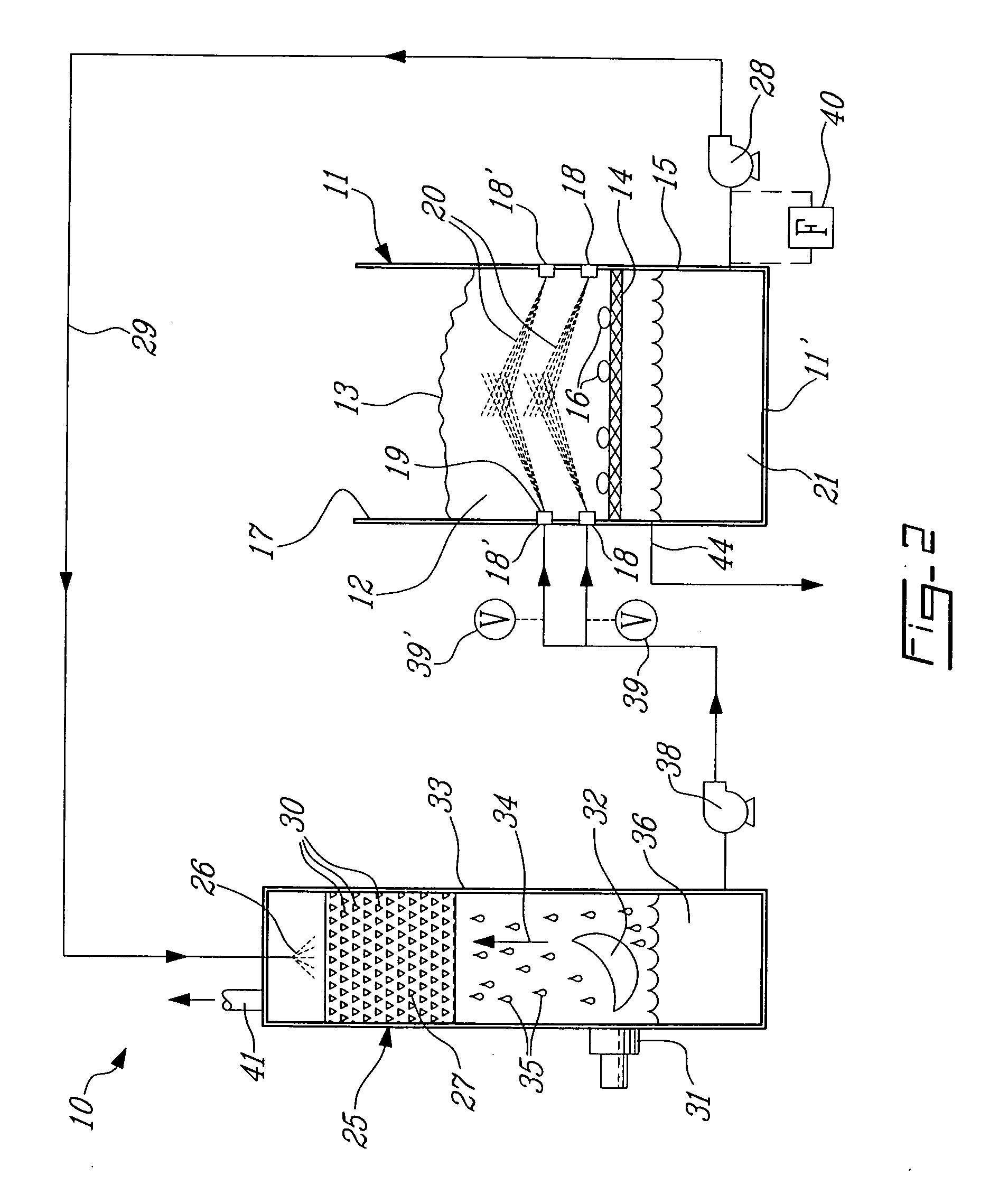
[0017]Referring now to the drawings and more particularly to FIG. 1, there is shown generally at 10 the snow melting system of the present invention. It is comprised of a snow melting housing 11 which can have many forms such as a stationary bin 11′ as shown in FIG. 2 or that bin or other housing could be mounted on a transport vehicle together with its associated equipment. The snow melting housing 11 defines therein a snow melting chamber 12 extending from above a support screen 14 which extends across the opposed side walls 15 of the housing 11 whereby to filter out debris 16 collected with the snow 13. The housing 11 has an open top end 17 to load snow into the snow melting chamber 12. The open top end 17 can also be provided with a suitable closure, not shown.

[0018]As hereinshown a plurality of water spray nozzles 18 are mounted in the housing side walls 15 all about the snow melting chamber 12. These water spray nozzles 18 have their jets 19 oriented upwardly at a slight angle...


PUM


Abstract

A snow melting system and a method is comprised of a snow melting housing defining a snow melting chamber therein. The housing has an opening to load snow in the snow melting chamber. A support is provided across the snow melting chamber to support snow therein elevated from a bottom wall of the snow melting chamber and to permit the passage of water therethrough to be collected in a water holding portion of the housing. A plurality of water spray nozzles are mounted in the housing about the snow melting chamber. A direct-contact water heater is provided for heating water to produce a supply of hot water to be fed at a constant pressure to the water spray nozzles for injection into the snow placed in the snow melting chamber for melting the snow. The direct-contact water heater is supplied water to be heated from the water holding portion of the housing. Excess water in the water holding portion is discharged and disposed of in the city drainage system.

Description

TECHNICAL FIELD[0001]The present invention relates to a snow melting system and its method of operation and particularly one which utilizes a direct-contact water heater to supply hot water to water jets disposed about a snow melting chamber for injection into snow placed therein.BACKGROUND ART[0002]Various types of snow melting systems are known for melting snow placed in a container and disposing of the water accumulating from the melted snow. However, such known devices lack in fuel efficiency and cannot achieve high melting rates per unit of fuel consumed or electricity used. They are therefore expensive to operate. Some of these devices are also very bulky and troublesome and require excessive maintenance to defrost the unit during cold weather periods when these units are not in use.[0003]Such devices have been designed to overcome the disadvantage of common snow removal methods used in large cities wherein large quantities of snow are stockpiled on the side of streets and par...

Claims


Application Information

Patent Timeline
IPC IPC(8): E01H5/10
CPCE01H5/102
Inventor DAVIES, TREVOR
Owner DAVIES TREVOR
Learn More