
Guide system for a roller blind of a sliding roof system

a technology of sliding roof and guide system, which is applied in the direction of roof, door/window protective device, shutter/movable grille, etc., can solve the problem of undesirable sagging

Inactive Publication Date: 2008-07-31
ROOF SYST GERMANY
View PDF10 Cites 31 Cited by
  • Summary
  • Abstract
  • Description
  • Claims
  • Application Information

AI Technical Summary

Benefits of technology

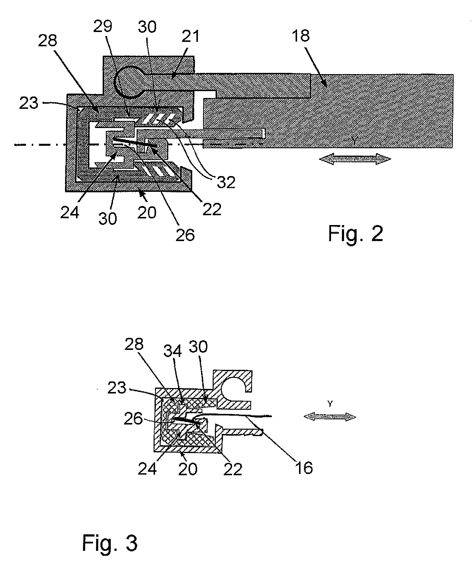
[0007]In one example, an intermediate guide is used to guide the slider. The intermediate guide is arranged within the guide rail and, in particular, can be moved transversely with respect to the longitudinal direction of the vehicle. This configuration makes it possible to design the intermediate guide to have little friction whereas, in the case of the pretensioning device, value can be placed in particular on the flexibility.
[0009]The intermediate guide in turn is mounted in the guide rail in a manner such that the intermediate guide can be moved transversely with respect to the longitudinal direction of the vehicle, which makes the system compact. The intermediate guide, which accommodates the slider, can be displaced transversely with respect to the longitudinal direction of the vehicle.
[0011]The intermediate guide sits in the guide rail in a manner such that the intermediate guide cannot be displaced in the longitudinal direction of the vehicle. The intermediate guide, which is designed to be displaced transversely with respect to the longitudinal direction of the vehicle, i.e. in the y-direction, is therefore mounted, with the roller blind fastened thereto, in a manner such that the intermediate guide floats in the y-direction.

Problems solved by technology

The sagging is undesirable for visual reasons, and, furthermore, accommodating the roller blind in the guide rails prevents flapping.

Method used


Image

  • Guide system for a roller blind of a sliding roof system
  • Guide system for a roller blind of a sliding roof system
  • Guide system for a roller blind of a sliding roof system

Examples


Embodiment Construction

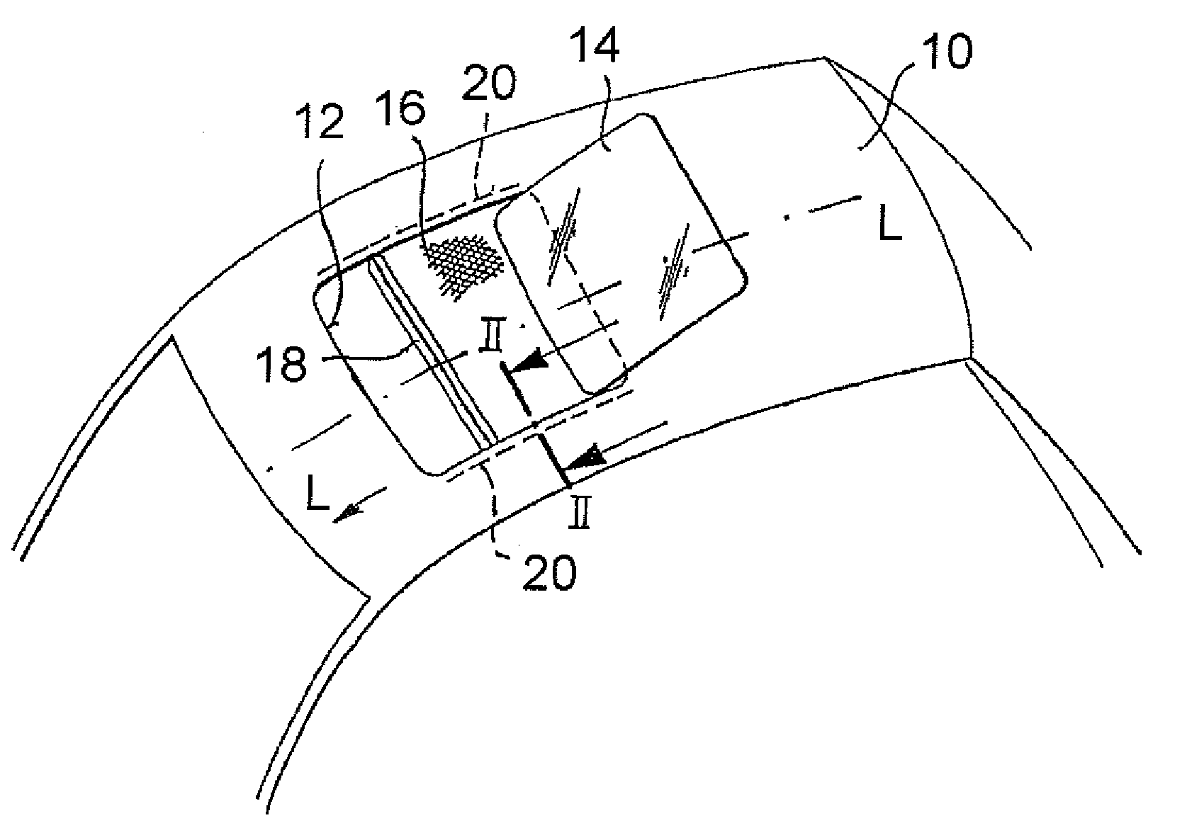
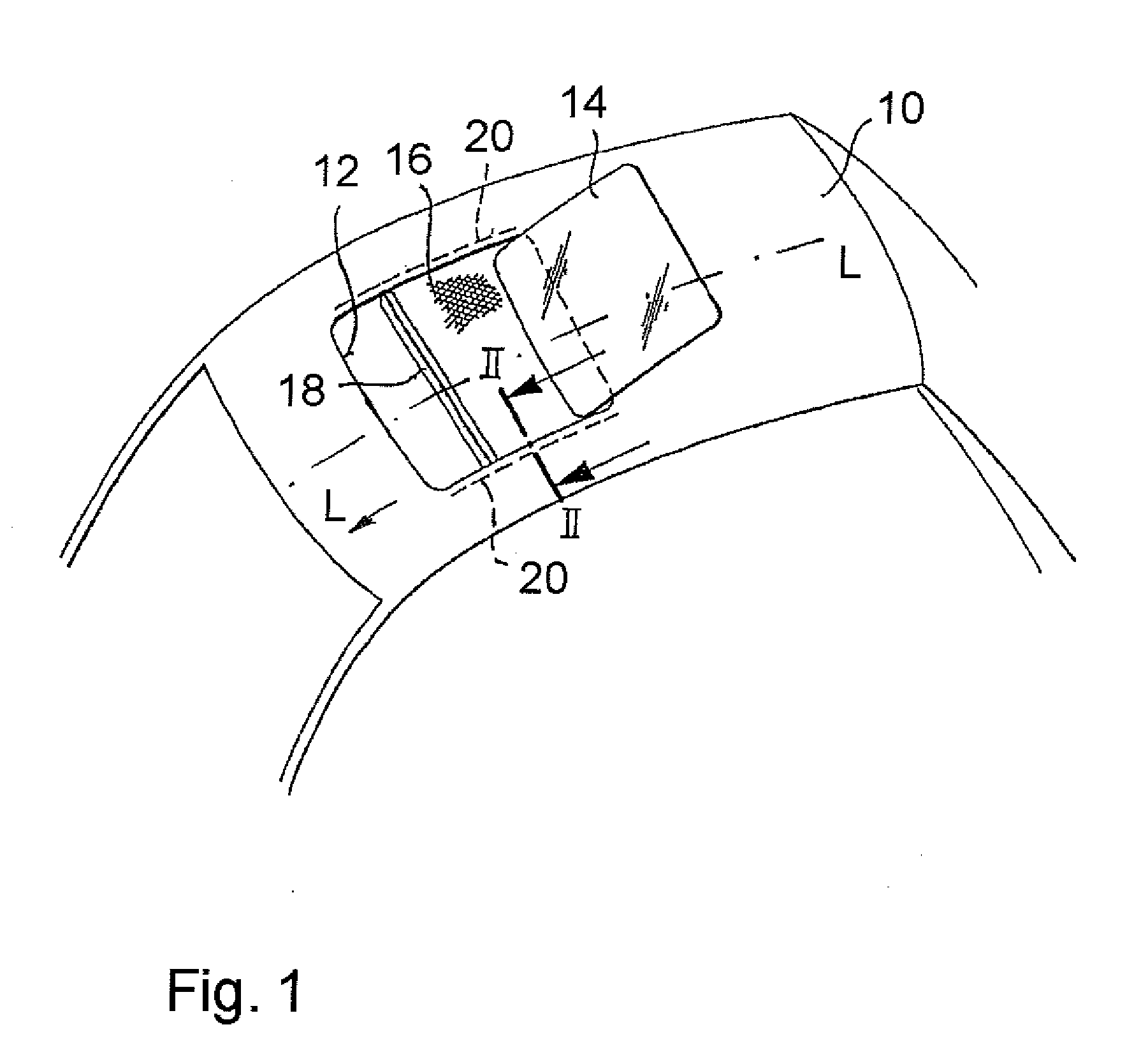
[0031]FIG. 1 shows a vehicle roof 10 with an opening 12. The opening 12 is assigned a cover 14 of a sliding roof system. The cover 14 can be displaced between a closed position in which the cover 14 closes the opening 12 and an open position, which is shown in FIG. 1. A roller blind 16 is arranged below the cover 14 and also below the opening 12. The roller blind 16 can be displaced, with respect to the vehicle, forwards (in a longitudinal direction L of the vehicle) and rearwards (counter to the longitudinal direction L of the vehicle), either manually or by being driven by a motor. If the roller blind 16 is pushed completely to the rear, the opening 12 is completely uncovered. Fresh air and sunlight then gain free access to a vehicle interior. If the roller blind 16 is pushed completely forwards, then the opening 12 is covered by the roller blind 16. Fresh air and sunlight can therefore pass into the vehicle interior only to a limited extent.

[0032]The roller blind 16 is composed o...


PUM


Abstract

A guide system for a roller blind of a sliding roof system has a guide rail and a slider that is fixed on the roller blind. The slider is accommodated in the guide rail such that the slider is displaceable in a longitudinal direction of a vehicle and carries the roller blind. A pretensioning device is arranged between the guide rail and the slider. The pretensioning device presses the slider outwards transversely with respect to the longitudinal direction of the vehicle in order to tension the roller blind.

Description

RELATED APPLICATIONS[0001]The application claims priority to European Patent Application 07 002 092.0, which was filed Jan. 31, 2007.BACKGROUND OF THE INVENTION[0002]The invention relates to a guide system for a roller blind of a sliding roof system.[0003]A roller blind, which can be displaced in a guide rail, can be fitted below an opening in a vehicle roof in order to cover the opening to a greater or lesser extent in accordance with vehicle occupant requirements. If the opening is to be uncovered, the roller blind is wound up on a winding spindle. The roller blind can then be pulled out from the winding spindle to cover the opening when needed. This operation can take place both manually and electrically. Longitudinal edges of the roller blind are accommodated in guide rails such that the roller blind is kept tensioned transversely with respect to the displacement direction. This prevents the roller blind from sagging into a vehicle interior when the roller blind is positioned be...

Claims


Application Information

Patent Timeline
IPC IPC(8): E06B9/58E06B9/40
CPCB60J7/0007B60J7/0015
Inventor BIEWER, CHRISTIANEIS, DIRKBOHM, HORST
Owner ROOF SYST GERMANY
Learn More