Equipment rack for trailers
Inactive Publication Date: 2008-07-31
INNOVATION LAW GROUP
39 Cites 4 Cited by
AI-Extracted Technical Summary
Problems solved by technology
Since there is a lot of theft from job sites and these tradesmen often must travel to and from many different sites in a relatively short period of time, ranging from daily to monthly, they ...
Method used
[0041]FIGS. 1, 3 and 6 also show an optional horizontal cross brace 72 provided to span across the back wall 14c (or/and the front wall 14a) of the trailer. This cross brace is spaced medially of the bottom and top ends of the legs 24 on the sides of the trailer, and has a dual function: first to provide a second layer of security to prevent opening of the rear doors, and second, as an access step for workman to access the load platform. The cross brace includes a pair of orthogonal extensions 73 adjacent the lateral ends of the brace 72 that are received in tubes 76a, 76b welded to the rear legs. The receiver tubes 76 may be supported by lower or/and upper diagonal braces 36. To retain the brace in place, aligned holes are provided in the receiver tubes and extensions, and a keeper pin 74 inserted. The keeper pin has a top head and preferably a hole near the bottom to receive a lock 64 to prevent the pin from being withdrawn. The lateral cross brace 72 is a safety, in the event a rear door springs open during bumpy travel. The cross brace 72 would prevent tools, materials and equipment from falling out and damaging following vehicles. In addition, it provides the additional function of a secondary lock at a jobsite, to prevent night-time or week-end theft. This is significant, as many workmen carry in excess of $10,000 worth of tradesman's tools and equipment in their trailers; loss means they are out of work.
[0043]FIG. 4 shows the funct...
Benefits of technology
[0019]The inventive straddle-type trailer rack provides the workmen additional, single-vehicle carrying capacity, with lock-in-p...
Abstract
Trailer racks, and more particularly to straddle-type trailer racks for closed trailers, which racks include a load platform supported by legs mounted directly to the trailer sub-frame, fit within the foot-print of the trailer wheels, do not interfere with side and rear doors, and are spaced from and not supported on the trailer body top nor rely on it for structural rigidity. The inventive straddle-type trailer rack can also be adapted for use with open trailers. A wide range of options are available, including equipment brackets secured to the legs that can also be used as steps, lockable keeper assemblies, dual function lockable safety cross braces, catwalk for the load platform, access ladder, and forward extensions. The inventive rack is also configurable in kit form.
Application Domain
Steps arrangementSupplementary fittings +1
Technology Topic
Structural rigidityVehicle frame +4
Image
Examples
- Experimental program(1)
Example
[0030]The following detailed description illustrates the invention by way of example, not by way of limitation of the scope, equivalents or principles of the invention. This description will clearly enable one skilled in the art to make and use the invention, and describes several embodiments, adaptations, variations, alternatives and uses of the invention, including what is presently believed to be the best modes of carrying out the invention.
[0031]In this regard, the invention is illustrated in the several figures, and is of sufficient complexity that the many parts, interrelationships, and sub-combinations thereof simply cannot be fully illustrated in a single patent-type drawing. For clarity and conciseness, several of the photographs or drawings show in schematic, or omit, parts that are not essential in that drawing to a description of a particular feature, aspect or principle of the invention being disclosed. Thus, the best mode embodiment of one feature may be shown in one photo/drawing, and the best mode of another feature will be called out in another photo/drawing.
[0032]All publications, patents and applications cited in this specification are herein incorporated by reference as if each individual publication, patent or application had been expressly stated to be incorporated by reference.
[0033]The line drawings of the Figures are numbered so that one skilled in the art of rack construction and use, by reference to the attached parts list will easily be able to understand the materials and method of construction and will be able to easily assemble the parts to achieve the functionality shown.
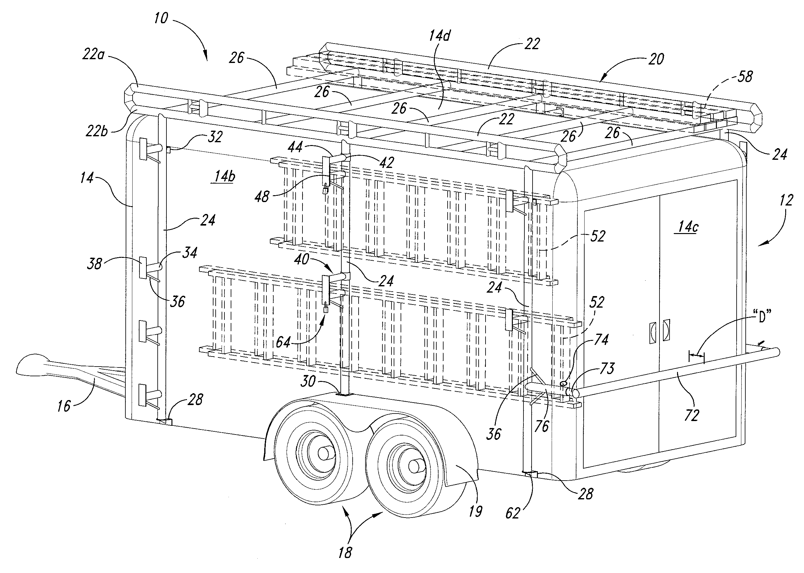
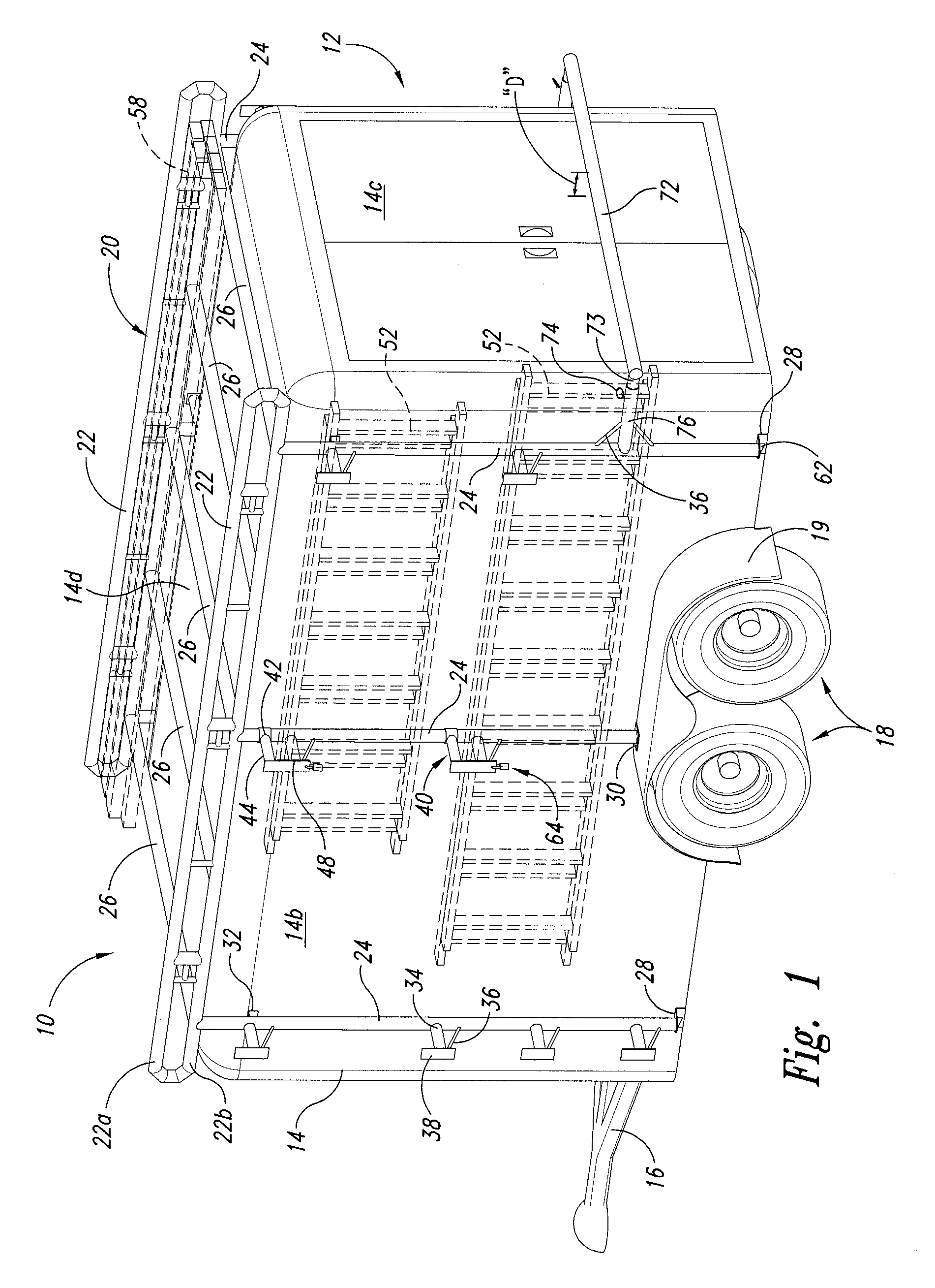
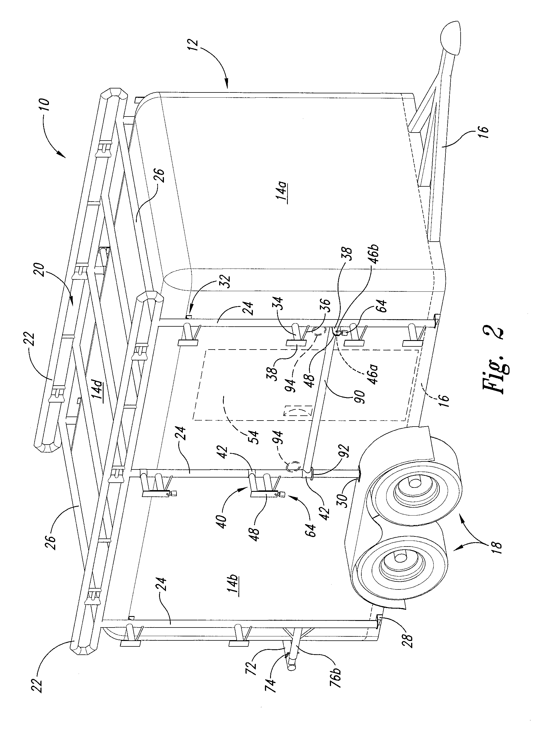
[0034]Considering FIGS. 1-3 as a related group, FIG. 1 is a perspective view from the left rear side of the inventive straddle-type trailer rack 10, mounted on a closed box trailer 12. FIG. 2 is a view from the right front side, and FIG. 3 is a rear elevation. In these figures, the trailer comprises a box body 14 mounted on a steel under-frame or chassis 16, and comprises front wall 14a (not shown in this view, see FIG. 2), two spaced side walls 14b, a rear wall 14c and a top 14d. The exemplary trailer 12 has a pair of rear doors and an optional side door (see FIG. 2). The chassis 16 is mounted on one or more axle/wheel assemblies 18, and may include an optional fender 19 over the wheel(s).
[0035]The inventive straddle-type trailer rack 10 comprises a load platform assembly 20 having a pair of opposed side rails 22, that are spaced apart by cross members 26. The platform 20 is supported by, in this example, six legs 24, three on each side, the tops of which are secured to the bottom member 22b of the side rail assembly 22. The distance between the bottom member 22b and the top member 22a of the side rail assembly 22 may be any suitable amount, and can be varied depending on the trade or use to which the rack is employed. Rings or hooks (not shown) may be welded or bolted to the side rail assembly as anchor points for lashings or tarps, as needed or desired.
[0036]The bottom of the legs are supported by frame brackets 28 that are bolted or welded to the under frame chassis 16. The bracket may include an optional gusset 62 where the load platform is designed to carry substantial weight. Where there is a fender, the leg bottom terminates in a foot 30 that sits on top the fender; underneath is the supporting bracket (best seen in FIG. 5). The leg is also spaced away from the side walls 14b by means of upper body spacer brackets 32. Note in this embodiment the middle legs are shorter than the forward and aft legs because of the presence of a fender. However, where there is no fender, the middle leg can extend down between the two tires and be bolted or welded directly to the frame there. Also, the fore-aft placement of the middle leg is selected to provide for even load balance. In a 2 wheel trailer, the middle leg may be over either of the axles on the fender as shown, or between the two axles. Generally, because of the weight of the frame and tongue, the proper placement is over the forward axle, or forward of the axle of a single wheel trailer.
[0037]The inventive straddle-type trailer rack also includes dual-function brackets 34, termed equipment brackets, that are supported by braces 36 and terminates in an up-standing lip plate 38. The brace permits the brackets 34 to be used as a step for the workman to access the top load platform 20. The brace 36 engages both the lip plate 38 and bracket tubing 34 at the outer end. Although the equipment bracket is shown as a piece of tubing, it may be flat steel plate welded either vertically or horizontally to the leg 24.
[0038]As shown, there are two or more step/equipment brackets per leg, aligned to permit horizontal loading of equipment, such as ladders 52. The ladders are securely retained on the brackets 34 by lip plate 38 and may be securely locked to prevent loss in transit or theft by keeper assembly 40. There can me more or less of the equipment brackets per leg to suit a particular tradesman's needs. For example, additional brackets may be provided to assist the workman climbing to the load platform, or for securing other equipment, such as hoses, and the like, or supplies (2×4s shown) 58.
[0039]By comparing FIGS. 1-3, note that the legs 24 are spaced away from the box body side wall 14b on the order of 1′-4″ as identified by the Arrow B (FIG. 3), and the load platform 20 is spaced above the top 14d by from 2-6″ as identified by Arrow A (FIG. 3). Note also by comparing those figures that the equipment, such as the ladders 52 are carried by the equipment brackets 34 within the wheel width of the axle/wheel assembly, so that the inventive straddle-type trailer rack 10 does not add width to the trailer.
[0040]As seen in FIG. 2 the legs are spaced so that they do not interfere with the opening of the side door 54. Optionally, a lock bar 90 may be provided to span between a middle leg and a forward leg. As shown the lock bar 90 is a tube, the aft end of which is welded to a sleeve 42 that pivotably rests on an annular plate 92 welded to the middle leg 24. The forward end of the bar terminates in a lock plate 48 having a hole or slot, 46a. The lock plate engages a plate 38 welded to the forward leg 24. The plate 38 includes a slot 46b. A padlock 64 is used to lock the plates 38/48 together to prevent the side door 54 from being opened. Optionally, instead of the lock bar 90, a pair of rings 94 may be welded to the legs, one on each of the middle and forward leg, and a chain (not shown) passed through the rings and the ends secured with a padlock.
[0041]FIGS. 1, 3 and 6 also show an optional horizontal cross brace 72 provided to span across the back wall 14c (or/and the front wall 14a) of the trailer. This cross brace is spaced medially of the bottom and top ends of the legs 24 on the sides of the trailer, and has a dual function: first to provide a second layer of security to prevent opening of the rear doors, and second, as an access step for workman to access the load platform. The cross brace includes a pair of orthogonal extensions 73 adjacent the lateral ends of the brace 72 that are received in tubes 76a, 76b welded to the rear legs. The receiver tubes 76 may be supported by lower or/and upper diagonal braces 36. To retain the brace in place, aligned holes are provided in the receiver tubes and extensions, and a keeper pin 74 inserted. The keeper pin has a top head and preferably a hole near the bottom to receive a lock 64 to prevent the pin from being withdrawn. The lateral cross brace 72 is a safety, in the event a rear door springs open during bumpy travel. The cross brace 72 would prevent tools, materials and equipment from falling out and damaging following vehicles. In addition, it provides the additional function of a secondary lock at a jobsite, to prevent night-time or week-end theft. This is significant, as many workmen carry in excess of $10,000 worth of tradesman's tools and equipment in their trailers; loss means they are out of work.
[0042]FIG. 3 shows that the inventive rack 10 does not interfere with opening of the rear access doors. As shown the access doors 54a, 54b are vertically hinged and open left/right, respectively. However, the inventive trailer rack legs 24 are placed on the sides so that the doors fully open more than 180°. Likewise, the door can be a full fold down type, hinged along the bottom, so that the door in the open position (down) forms a ramp. This trailer configuration is frequently used for vehicle transport. Likewise, the horizontally hinged door can be split, half hinged at the top, and half at the bottom, or 40/60 top/bottom. The bottom portion (half or ⅔rds, for example) serves as a ramp, and the top portion serves as a sheltering overhang.
[0043]FIG. 4 shows the function of the keeper assembly 40. The equipment bracket horizontal tube 34 is welded to the leg 24, is strengthened by diagonal brace rod 36, and terminates in an up-standing lip plate 38 having a lock slot 46b. The keeper assembly 40 includes a horizontal tube 44 welded to a sleeve 42, and it terminates at its outer end in a downward projecting lip plate 48 having a lock hole 46a. The length of tube 44 is enough longer than the tube 34 to permit the lip plate 48 to be dropped over lip plate 38, the hole and slot 46a, 46b aligned, and the keeper 40 locked to the equipment bracket with padlock 64. Note that an array of holes or holes and slots, or dual slots can be provided in the lip plate 36 and keeper plate 48 to accommodate various widths of ladder rails, equipment or materials locked in place. In addition, the keeper plate and lip plate can be longer to provide more carrying capacity.
[0044]FIG. 5 shows the middle leg 24 terminating at its bottom end in a foot plate 30 that rests on top of the fender 19. A vertical bolt 60 is welded into a central hole of the footplate 30. The bolt projects through a hole in the fender, and thence through a frame bracket 28 and a lock nut secures the bracket to the bolt. The bracket is also bolted to the frame with horizontal bolts 60 as shown, As noted above the frame brackets may include reinforcing gussets, 62 (see FIG. 1).
[0045]FIG. 6 shows the inventive rack mounted on a trailer frame as in FIG. 1 with the cross brace removed to more clearly show the receiver tubes 76a and 76b. In addition, this figure shows an optional catwalk 50 mounted on the load platform assembly 20. That catwalk can be bolted to the top of the load platform as an after-market option.
[0046]In addition, an optional access ladder 66 is shown. The ladder may be secured to the fore or aft ends of the catwalk rails 82 via pivots 80, so that the ladder can fold up and over to a stowed position as shown by Arrow C. Optionally, and preferably, the ladder may fold up horizontally, and then slide under the catwalk in the space A (see FIG. 3). Where the ladder 66 is secured to the front end of the catwalk, it is preferred to be permanently secured to the catwalk, and have rubber or polymeric bumpers spacing it from the front end wall 14a (FIG. 1). The ladder may also be secured to or hung from a cross member 26, and may be an add-on accessory, formed as a separate structure that is bolted or pinned to the cross members (e.g., for the kit version of the inventive rack), or may be integral to the load platform, welded to the cross members. For a rear or side-mounted ladder, the bottom of the ladder may extend closer to, or include sliding legs that permit it to extend all the way to the ground, or/and be slanted, as desired. Optionally, the bottom ends of the ladder side rails may be curved toward the door and terminate in rubber bumpers to prevent the ladder from banging into and damaging the door.
[0047]FIG. 7 shows the inventive rack in a kit form, in which two side rail assemblies 22 are provided. Note the orthogonal sleeves 76a, 76b. As shown, in this kit example, the frame brackets 28, the equipment brackets 34 and the keeper assembly 40 are pre-assembled on the corner legs 24b. The foot plate 30 is preassembled on the shorter middle legs 24a, but the under fender brackets 28 are provided separately. The body spacer brackets 32 are preassembled on the legs. Bolts as needed, of various sizes are provided, along with assembly and mounting instructions. This kit can be shipped by freight, UPS, FedEx Ground, or other transport direct to the customer. Various accessories, such as the cross braces of FIGS. 1 and 3, the ladder and catwalk of FIG. 6 and the forward extension of FIG. 9 are optional items that can also be shipped, whether with the kit or the dealer installation, or later.
[0048]The sleeves 76a receive the legs 24a, 24b, and the sleeves 76b receive the cross braces 26, of which from 3-6 are provided, 5 being shown in this example. Four corner legs 24a are shown as including a pre-welded bracket 28. Two middle legs24b with the lockable keeper assembly 40 are provided. The footplate 30 is provided as pre-welded onto the bottom of the middle legs 24b, and the separate bracket 28 is provided. The cross braces 26 are fitted into the receiving sleeves 76b and the pins 74 are fitted into the aligned holes and the semi-circular keeper spring snapped over the projecting bottom end of the pins. Alternately, bolts 60 may be used to secure all parts together. The length of the side rail assemblies, the number of legs and cross members may be varied depending on the length of the trailer to which secured, shorter/fewer for short trailers, and longer/more for long trailers.
[0049]To assemble the kit, the corner legs are fitted into the appropriate sleeves 76a, and the two sides raised up vertically, and the cross members inserted in sleeves 76b and pinned together. The unit is then walked over the trailer, the middle legs inserted, and the brackets bolted to the frame. Alternately, the legs can be bolted first to the frame, one side rail placed on the legs, cross members inserted, and the second side rail attached. Bolts are presently preferred over pins to reduce flexure and provide needed rigidity in the entire rack assembly.
[0050]FIG. 8 shows an open trailer 86 having a partial load or bin box 68 and a rear ramp 56 fitted with the straddle-type rack 10 of the present invention, mounted as with the closed trailer of FIGS. 1-7 to the frame 16 and fender 19 via brackets 28. In addition, cross braces of tubing or tensioned cables 84 may be applied to the front and sides of the open framework of the rack, as shown. Added diagonal bracing 36 between the rear legs and the cross member may be used at the rear or/and front or and mid-leg position. Note that in this configuration, a tarp, canvas or rip-stop, water-proof tent fabric can be secured to the inventive trailer rack with bungees or rope, thus providing some weather protection, e.g. for gardening equipment including tractors, weed whackers, blowers, trimmers, edgers and implements, or for household goods being moved, such as furniture, bedding and the like. Optionally, hooks can be provided on the frame rails, cross members, legs and reinforcing braces to engage grommets on the tarps or tenting material, or from which to hang plywood, chipboard or OSB sheets.
[0051]FIG. 9 is an isometric drawing showing a forward extensions E of the rack side rails 22 forward of the front wall of the trailer 14a. The forward end is supported by a pair of legs 24a, 24b that rest on a support plate 88 that is bolted to the converging frame members 16 just aft of the hitch as shown. This permits carrying longer supplies and equipment on the load platform 20. As shown, such equipment or materials can extend over the bed or/and cab of a towing pick-up truck without interfering with operation, turning, going over bumps or the like.
INDUSTRIAL APPLICABILITY
[0052]It is clear that the inventive trailer straddle-type trailer rack has wide applicability to trailers of all types, and particularly to job-site and vehicle transport covered trailers. It should be under-stood that various modifications within the scope of this invention can be made by one of ordinary skill in the art without departing from the spirit thereof and without undue experimentation.
PUM


Description & Claims & Application Information
We can also present the details of the Description, Claims and Application information to help users get a comprehensive understanding of the technical details of the patent, such as background art, summary of invention, brief description of drawings, description of embodiments, and other original content. On the other hand, users can also determine the specific scope of protection of the technology through the list of claims; as well as understand the changes in the life cycle of the technology with the presentation of the patent timeline. Login to view more.