Low leakage spring clip/ring combinations for gas turbine engine

a gas turbine engine and low leakage technology, applied in the direction of machines/engines, stators, lighting and heating apparatus, etc., can solve the problems of low cooling air flow through various existing spring clip assemblies, less available, or not available, and not providing a level of precision and accuracy for cooling

Active Publication Date: 2008-07-31
SIEMENS ENERGY INC
View PDF21 Cites 41 Cited by
  • Summary
  • Abstract
  • Description
  • Claims
  • Application Information

AI Technical Summary

Problems solved by technology

In “open cooling” approaches, such air enters a hot gas flow path downstream of the combustor and may be less available, or not available, for such primary purposes.
As compressed air is used for cooling components, such as through open cooling of more downstream components, this loss of compressed air that would otherwise enter the combustor may result in higher than desired NOx emissions.
However, the level and variability of cooling air flow through various existing spring clip assemblies does not provide a level of precision and accuracy for cooling, and consequent cooling efficiency, that is desired for more advanced gas turbine engine systems.

Method used


Image

  • Low leakage spring clip/ring combinations for gas turbine engine
  • Low leakage spring clip/ring combinations for gas turbine engine
  • Low leakage spring clip/ring combinations for gas turbine engine

Examples


Embodiment Construction

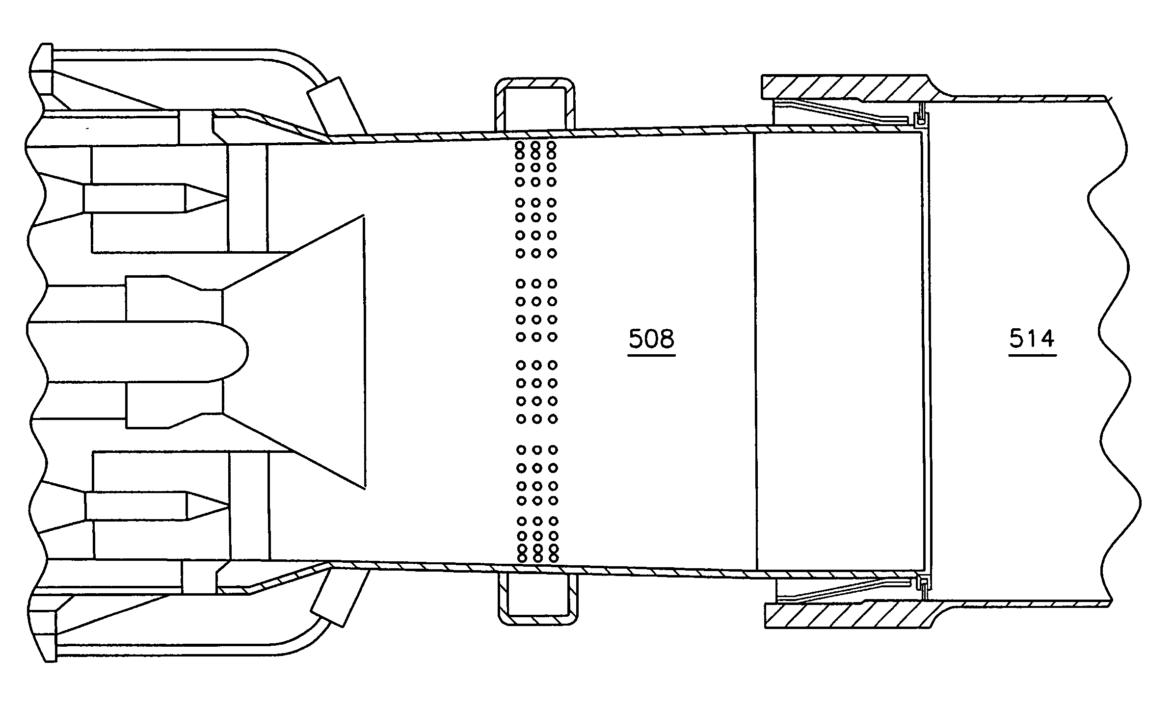
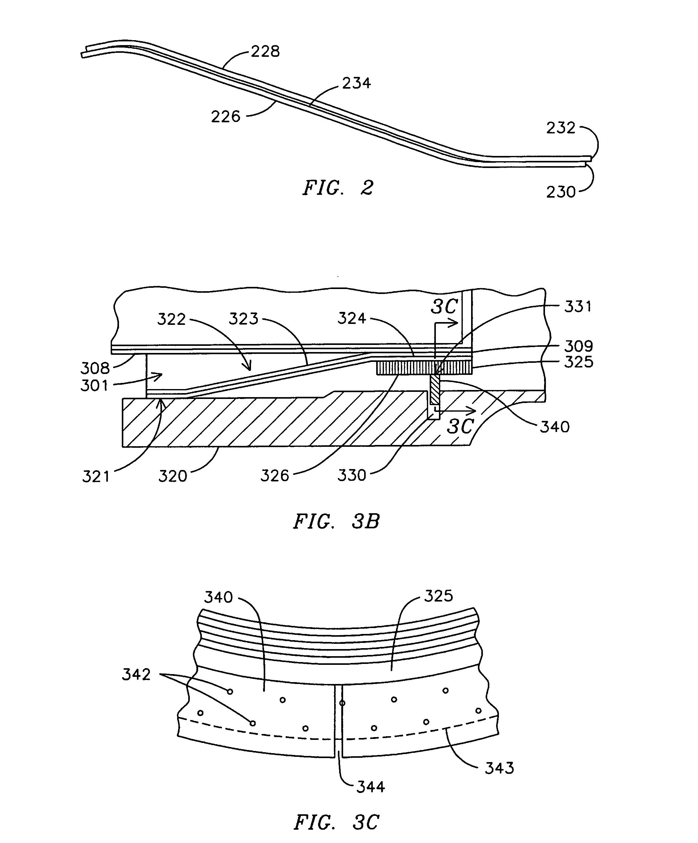
[0012]The present inventor has identified variable leakage to exist at spring clip assemblies at the junction of a combustor and a transition. This may include unit-to-unit variation. It was perceived that resolution to obtain a more precise, desired level of leakage to effectuate cooling, without unneeded losses, could provide additional compressed air to the combustor and provide for lower emissions. Following such identification and analysis the present inventor conceived a more advanced cooling system comprising a spring clip assembly combined with a piston-type spring-metal ring. This solution, exemplified by embodiments described below and depicted in the figures, achieves low and uniform defined leakage that is sufficient to provide a specified level of cooling. Embodiments also provide a desired structural integrity and seal redundancy. The savings in cooling air provides for improved combustion and emissions.

[0013]FIG. 1A provides a schematic cross-sectional depiction of a ...


PUM


Abstract

A combustor-to-transition seal (301) includes a spring clip assembly (322, 422, 522) and a first spring metal ring (340, 441) or a ring assembly (440,540) that includes the first spring metal ring (441) and a second spring metal ring (442). Such combustor-to-transition seal (301) provides a first seal (321) and a second seal (331, 531) when at a junction of a combustor (108, 308, 508) and a transition (114, 314, 514). In an embodiment, the first spring metal ring (340) has a plurality of apertures (342) through the ring (340) that provide effusion cooling of the ring (340). The plurality of apertures (342) regulates a flow of cooling fluid to maintain an acceptable temperature of the ring (340). In an alternative embodiment, the second spring metal ring (442) has grooves (446) that regulate a flow of cooling fluid to maintain an acceptable temperature of the ring assembly (440).

Description

BACKGROUND OF THE INVENTION[0001]A modern gas turbine engine, such as is used for generation of electricity at power plants, is a multi-part assembly of various adjacent components, many of which are subjected to mechanical and thermal stresses over long periods of operation. Mechanical stresses to various components result from one or more of vibrational, low cycle (and other thermally related), and other types of stress contributors. As to direct thermal stresses, operating temperatures in some gas turbine engine combustion chambers may reach or exceed 2,900 degrees Fahrenheit, and components of such combustion chambers are cooled and / or provided with thermal barrier coatings to address exposure to such elevated temperatures.[0002]When cooling is used to maintain a component below a specified temperature, often compressed air from the compressor is diverted to pass through a cooling passage. In “closed cooling” approaches, such air, after cooling, continues to the combustor entran...

Claims


Application Information

Patent Timeline
Patent Type & Authority Applications(United States)
IPC IPC(8): F02F11/00
CPCF01D9/023F23R2900/00012F05D2260/20F23D2214/00F23R3/60F05D2240/57
Inventor RYAN, WILLIAM R.
Owner SIEMENS ENERGY INC
Why Eureka
Try Eureka