Polarized electromagnetic relay and coil assembly

a technology of polarized electromagnetic relays and coil assemblies, applied in electromagnetic relays, electrical apparatus, electromagnetic relay details, etc., can solve the problems of increasing manufacturing costs, and achieve the effects of reducing manufacturing costs, improving response (or operating time), and simplifying the driving configuration of magnetic movable elements

Active Publication Date: 2008-07-31
FUJITSU COMPONENENT LTD
View PDF11 Cites 29 Cited by
  • Summary
  • Abstract
  • Description
  • Claims
  • Application Information

AI Technical Summary

Benefits of technology

[0009]It is an object of the present invention to provide a polarized electromagnetic relay including an electromagnet assembly configured in such a manner that a magnetic movable element including a permanent magnet is linearly shifted due to the excitation of an electromagnet in a direction parallel with a center axis of a coil, wherein the structure and driving configuration of the magnetic movable element can be simplified, so that response (or operating time) can be improved and outside dimensions and manufacturing costs can be effectively reduced.
[0010]It is another object of the present invention to provide a polarized electromagnetic relay in which an electromagnet includes at least three coil terminals, wherein an automatic winding process for connecting a wire to each coil terminal and thereby forming a coil on a bobbin can be safely and accurately performed.
[0011]It is a further object of the present invention to provide a coil assembly adapted to be used in a polarized electromagnetic relay, wherein an automatic winding process for connecting a wire to each of at least three coil terminals and thereby forming a coil on a bobbin can be safely and accurately performed.

Problems solved by technology

Further, in this configuration, the U-shaped iron core of the electromagnet and the U-shaped yokes of the magnetic movable element cooperate with each other by simultaneously exerting magnetic effects at their longitudinally opposite ends, so that in order to reduce unevenness of operational characteristics, it is necessary to improve the dimensional accuracy of these components, which may increase manufacturing costs.

Method used


Image

  • Polarized electromagnetic relay and coil assembly
  • Polarized electromagnetic relay and coil assembly
  • Polarized electromagnetic relay and coil assembly

Examples


Embodiment Construction

[0045]The embodiments of the present invention are described below in detail, with reference to the accompanying drawings. In the drawings, the same or similar components are denoted by common reference numerals.

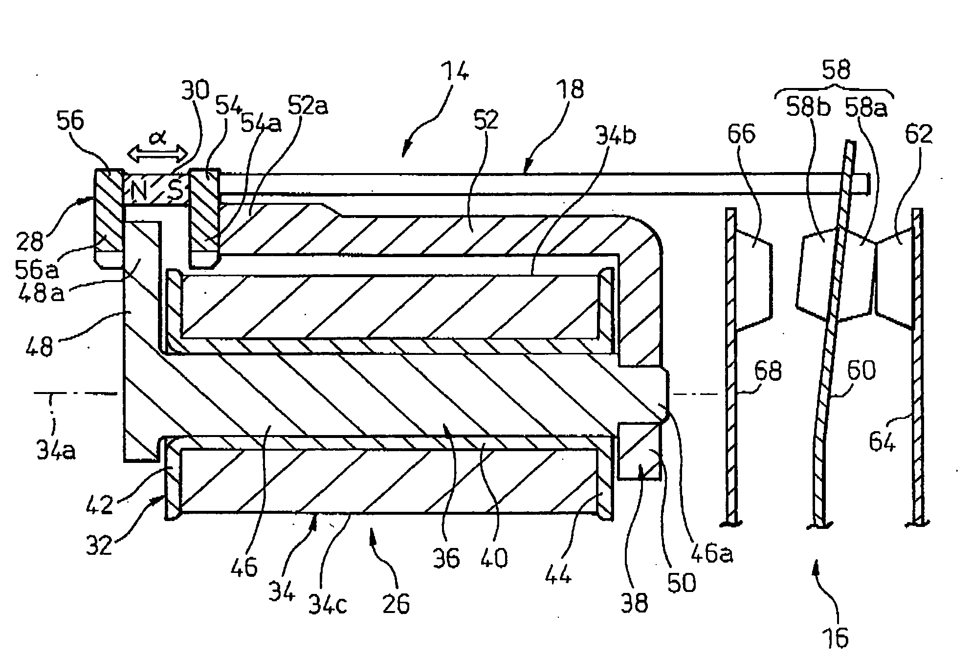
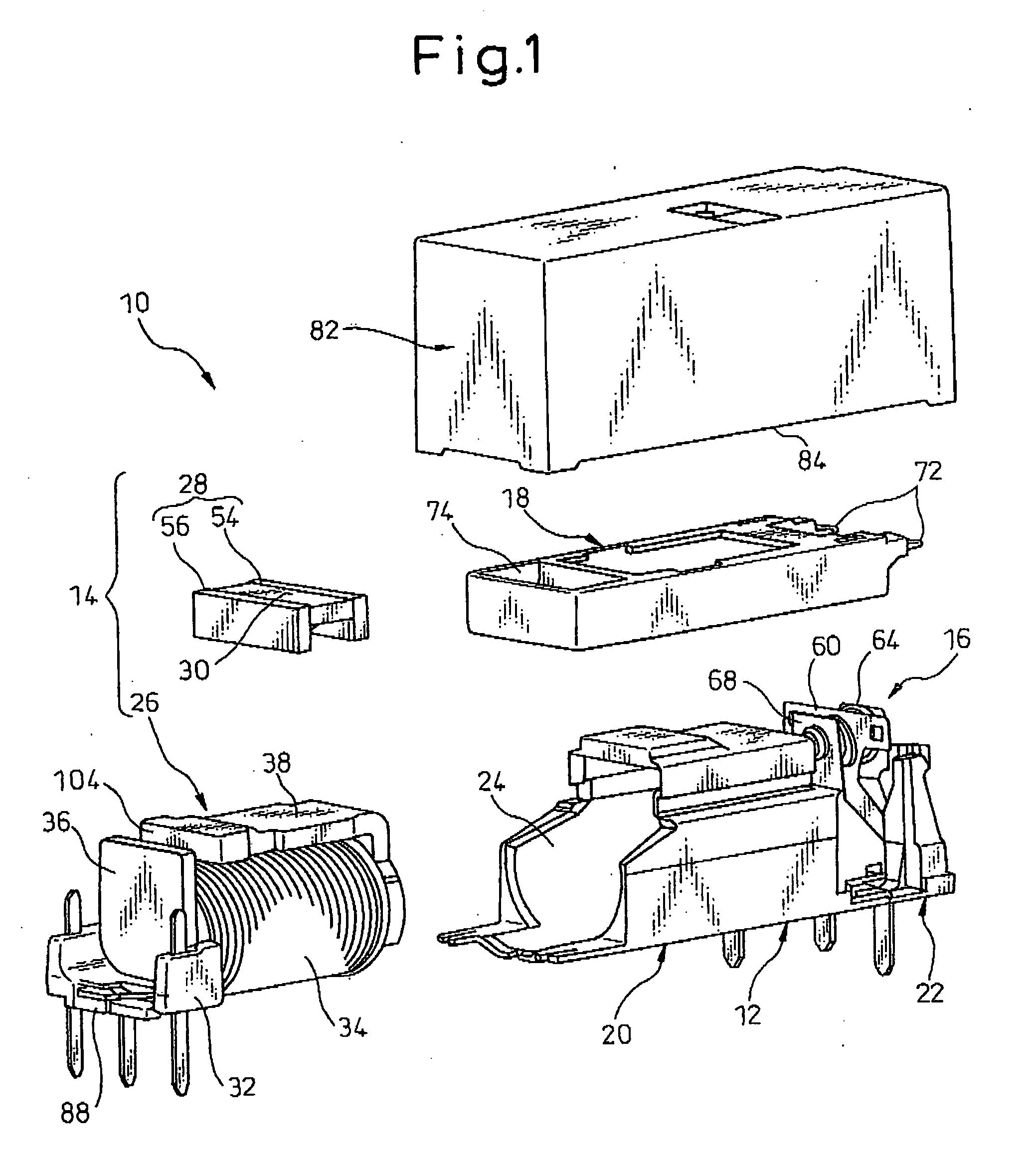
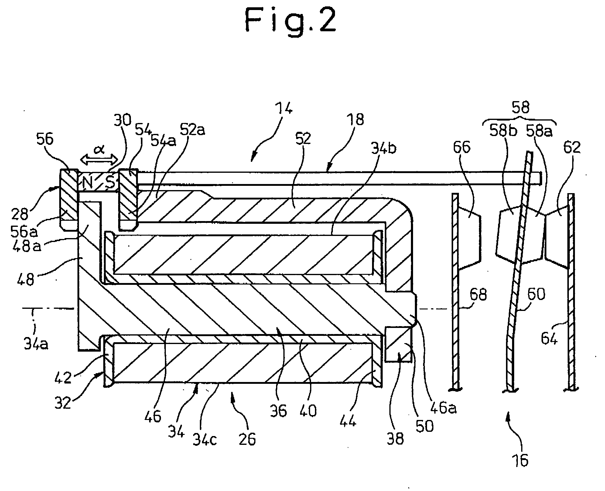
[0046]Referring to the drawings, FIG. 1 shows a polarized electromagnetic relay 10 according to an embodiment of the present invention in an exploded view clearly showing several components, and FIG. 2 diagrammatically shows components of the polarized electromagnetic relay 10 for clarifying their functions. Further, FIGS. 3 and 4 respectively show other components of the polarized electromagnetic relay 10.

[0047]As shown in FIGS. 1 and 2, the polarized electromagnetic relay 10 includes a base 12; an electromagnet assembly 14 fitted to the base 12; a contact section 16 fitted to the base 12 and insulated from the electromagnet assembly 14; and a force transfer member 18 disposed between the electromagnet assembly 14 and the contact section 16, the force transfer member 18 bei...


PUM


Abstract

A polarized electromagnetic relay including an electromagnet assembly, a contact section insulated from the electromagnet assembly, and a force transfer member disposed between the electromagnetic assembly and the contact section. The electromagnet assembly includes an electromagnet, an armature driven by the electromagnet, and a permanent magnet carried on the armature. The armature includes first and second electrically conductive plate elements holding the permanent magnet therebetween in a direction of magnetization of the permanent magnet and disposed to orient the direction of magnetization in parallel with the center axis of the coil. The armature is arranged linearly movably in a direction parallel with the center axis in a state where a part of the first electrically conductive plate element is inserted into a space between the outer peripheral region of the iron core head portion and the distal end region of the yoke major portion.

Description

BACKGROUND OF THE INVENTION[0001]1. Field of the Invention[0002]The present invention relates to a polarized electromagnetic relay. The present invention also relates to a coil assembly adapted to be used in a polarized electromagnetic relay.[0003]2. Description of the Related Art[0004]A polar or polarized electromagnetic relay, wherein an electromagnet assembly including an electromagnet and a permanent magnet as well as a contact section including a plurality of contact members are insulated from each other and attached to a base, and wherein a force transfer member shiftable under an action of the electromagnet assembly to make the contact members of the contact section open or close is disposed between the electromagnet assembly and the contact section, has been known in the art. For example, Japanese Unexamined Patent Publication (Kokai) No. 58-181227 (JP-A-58-181227) discloses a polarized electromagnetic relay of this type, in which an electromagnet assembly is configured so t...

Claims


Application Information

Patent Timeline
Patent Type & Authority Applications(United States)
IPC IPC(8): H01H51/22
CPCH01H50/043H01H50/443H01H50/642H01H2051/2218H01H51/2227H01H2050/446H01H51/2209
Inventor KUBONO, KAZUOSATO, SHINICHI
Owner FUJITSU COMPONENENT LTD
Why Eureka
Try Eureka