Unlock instant, AI-driven research and patent intelligence for your innovation.
Image displaying method and image displaying apparatus
Inactive Publication Date: 2008-07-31
SHARP KK
View PDF13 Cites 18 Cited by
Summary
Abstract
Description
Claims
Application Information
AI Technical Summary
This helps you quickly interpret patents by identifying the three key elements:
Problems solved by technology
Method used
Benefits of technology
Benefits of technology
[0018]The present invention is made in view of the foregoing conventional problem, and an object is to realize an image displaying method and an image displaying apparatus which can ensure an improved moving picture quality without causing a decrease in luminance or flicker.
[0020]With this structure, display outputs in the sub-frame A period and B period are performed with image signals αA, αB, βA, and βB satisfying the following condition.α≦αA<β, αB≦α, α<βA≦β, β≦βB, DA≦D, D≦DB, DA<DB.That is, the difference between the two adjacent regions in the image signal decreases in the sub-frame A period, and increases (emphasized) in the sub-frame B period. In this way, the present invention provides an effect of improvement in moving picture quality of a hold-type display device without causing a decrease in luminance or flicker.
Problems solved by technology
However, in the method of Patent Document 1, it is difficult to estimate an image signal between the two frames with perfect accuracy, and therefore defective operation due to estimation error is always possible.
However, it is difficult to estimate an image signal between the two frames with perfect accuracy, and therefore defective operation due to estimation error is always possible. FIG. 40 (d) shows an example of virtual frame in the middle time point.
However, there is a level difference in the distribution waveform of the luminance level integrated amount in the vicinity of the left edge (the circle portion of FIG. 42) of the 75% region due to an estimation error of a virtual frame.
This causes degradation of picture quality, such as image noise.
Method used
Image
Click on the blue label to locate the original text in one second.
Reading with bidirectional positioning of images and text.
Examples
first embodiment
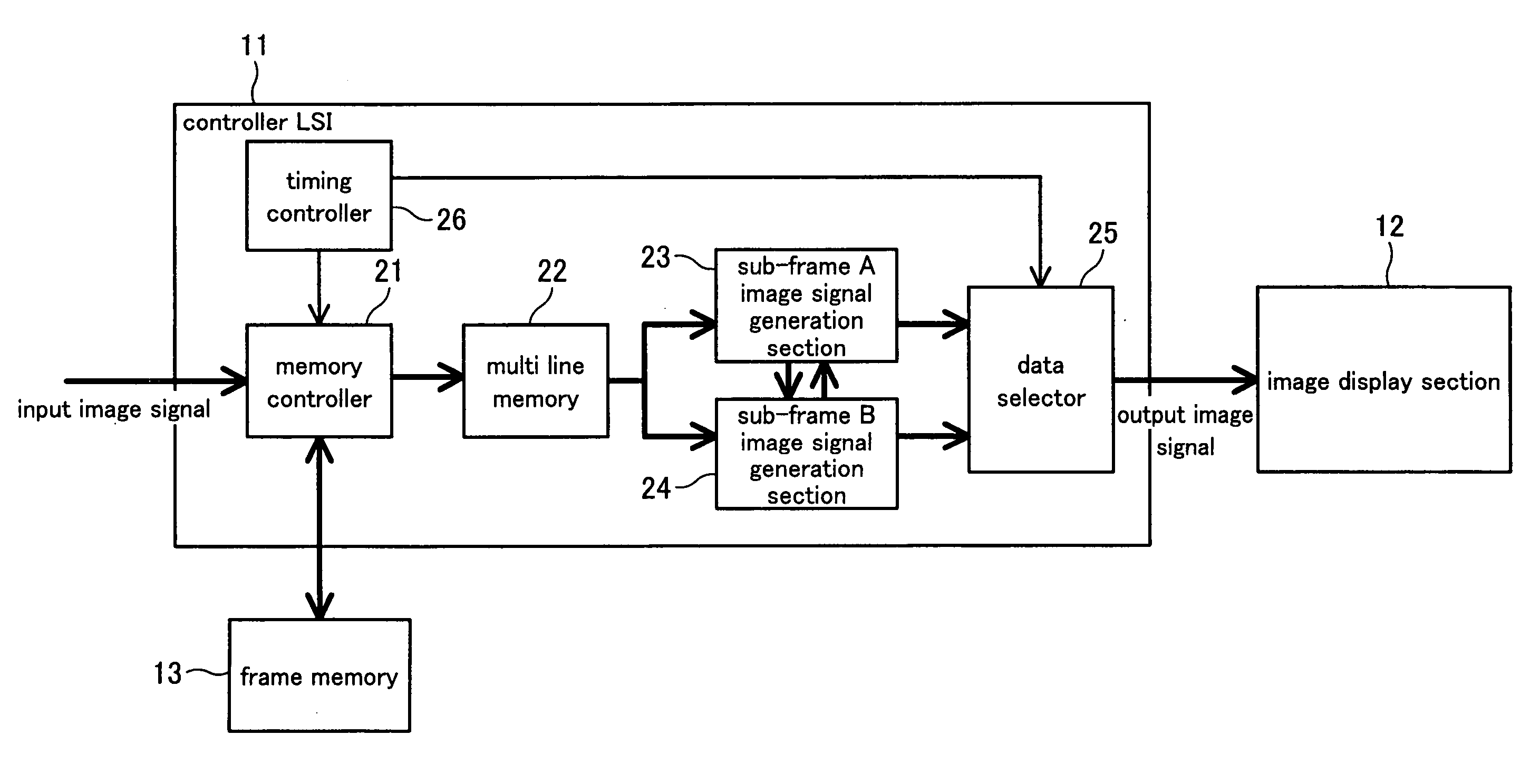
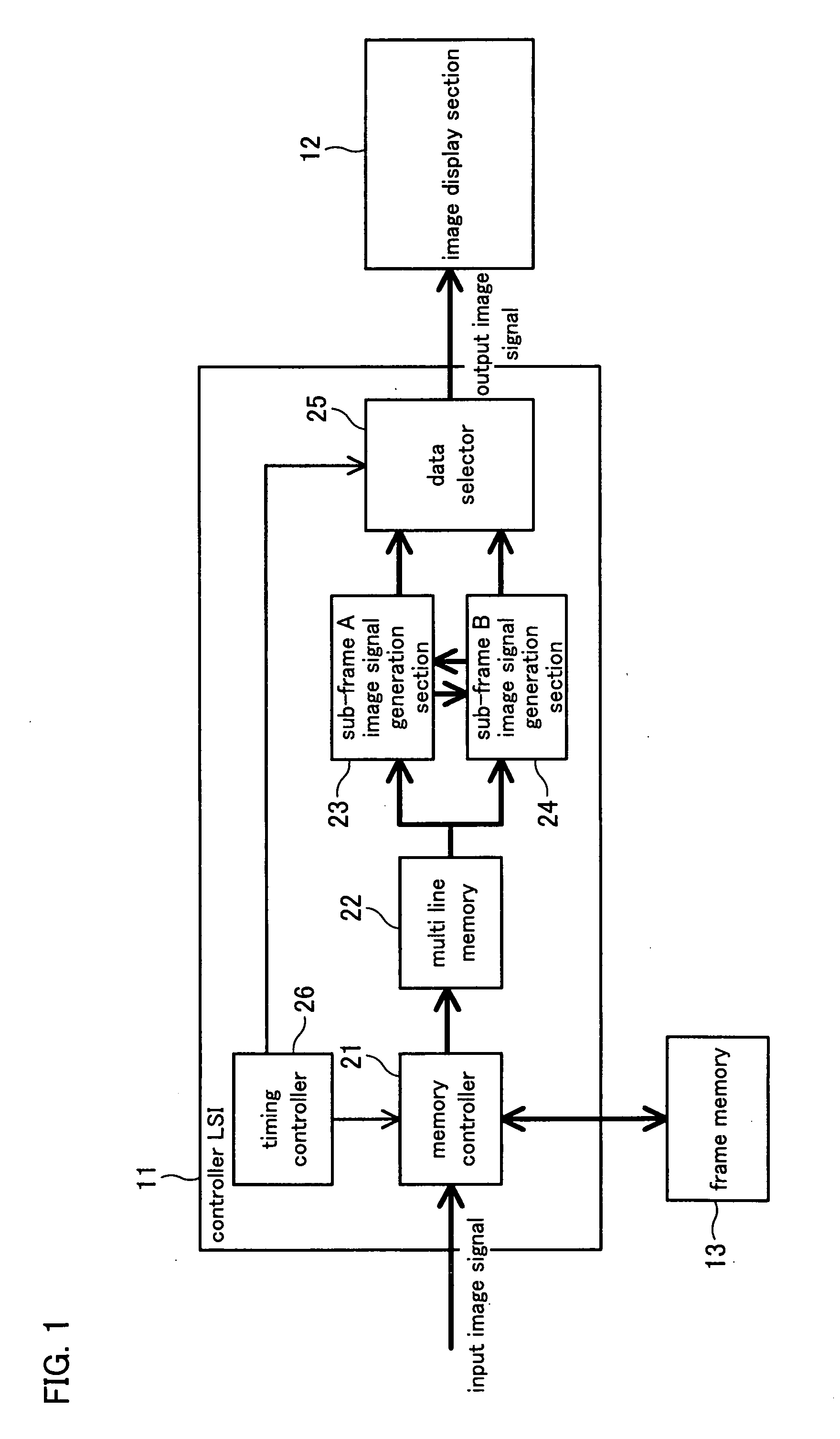
[0121]FIG. 1 shows a structure of an image displaying apparatus according to the present embodiment. In this image displaying apparatus, a controller LSI 11 (display control section) is connected to an image display section 12, such as a liquid crystal panel, and a frame memory 13. The controller LSI 11 includes a timing controller 26, a memory controller 21, a multi line memory 22, a sub-frame A image signal generation section 23, a sub-frame B image signal generation section 24, and a data selector 25.
[0122]The timing controller 26 generates timings of a sub-frame A period and a sub-frame B period which are two divisional periods of a 60 Hz input frame period, so as to control the memory controller 21 and the data selector 25.
[0123]The memory controller 21 first (1) writes a 60 Hz input image signal into the frame memory 13, and then (2) transmits an image signal of 1 frame having been written into a frame memory 13 to the multi line memory 22 at a frame period of 120 Hz. That is,...
second embodiment
[0189]In the present embodiment, the determining method of the sub-frame A and B is the same as that of First Embodiment, but the 1 frame period is divided into 3 sub-frames. The first and the final sub-frames are determined as the sub-frame A, and the middle sub-frames are determined as the sub-frame B. The period length of the sub-frame B is twice a single period of the sub-frame A. The figures to be referred are the same as those in First Embodiment. The difference from First Embodiment is the following block function.
[0190]The timing controller 26 divides a 60 Hz input frame period into 3 parts, generates timings of two sub-frame A periods and a single sub-frame B period, and controls a memory controller and a data selector.
[0191]The memory controller 21 (1) writes a 60 Hz input image signal into a frame memory,
(2) transmits the image signals of 1 frame written into the frame memory to a multi-line memory at a speed according to the sub-frame period. That is, three rounds of the...
third embodiment
[0194]In the present embodiment, in displaying the Nth frame, a virtual sub-frame M is generated as an estimated value based on the image signal of the input (N−1)th frame and the input Nth frame. The virtual sub-frame M resides in the middle time point between the input (N−1)th frame and the input Nth frame. The display 1 frame period is divided into the two sub-frames identical in period length, one of which is a sub-frame A period in which a mean image signal of pixels in a certain range in the vicinity of the target pixel of the virtual sub-frames M is outputted, and the other is a sub-frame B period in which an image signal for emphasizing the difference between the input image signal of the target pixel and the mean input image signal of the Nth frame input image signals to the pixels within the reference range in the vicinity of the target pixel is outputted.
[0195]FIG. 19 shows a structure of the image displaying apparatus. In this image displaying apparatus, a controller LSI...
PUM
Abstract
In on embodiment of the present invention, an image displaying apparatus is disclosed which divides 1 frame into plural sub-frame periods, and modifies the image signals in the following manner in the case of receiving an image of a frame in which a region denoted by an image signal α or an image signal close to the image signal α and a region of another image signal β or an image signal close to the image signal β are adjacent to each other. Specifically, the image displaying apparatus carries out display, in at least one sub-frames period A, with a modified image signal so that the difference with the image signal of the other region becomes smaller, and in at least one other sub-frames period B, with a modified image signal so that the difference with the image signal of the other region becomes more significant, in the vicinity of the boundary between the region of the image signal α and the region of the image signal β. In this way, an embodiment of the present invention provides an effect of improvement in moving picture quality of a hold-type display device without causing a decrease in luminance or flicker.
Description
TECHNICAL FIELD[0001]The present invention relates to an image displaying apparatus such as a liquid crystal display apparatus and an image displaying method thereof.BACKGROUND ART[0002]An image displaying apparatus using a hold-type display apparatus such as a liquid crystal display apparatus has a problem of degradation of moving picture quality (indistinct edge).[0003]The following explains the degradation of moving picture quality (indistinct edge) in a conventional hold-type display apparatus with reference to FIG. 29. FIG. 29 shows a case where a region of an image signal 75% in luminance level moves in the horizontal direction on a background of a image signal 25% in luminance level.[0004]FIG. 30 shows luminance level distribution for pixels on a 1-horizontal line on a picture, with respect to an input image signal supplied to a frame for such image display.[0005]FIG. 31 shows time transition in a display luminance distribution of a conventional hold-type display apparatus in...
Claims
Application Information
Patent Timeline
Application Date:The date an application was filed.
Publication Date:The date a patent or application was officially published.
First Publication Date:The earliest publication date of a patent with the same application number.
Issue Date:Publication date of the patent grant document.
PCT Entry Date:The Entry date of PCT National Phase.
Estimated Expiry Date:The statutory expiry date of a patent right according to the Patent Law, and it is the longest term of protection that the patent right can achieve without the termination of the patent right due to other reasons(Term extension factor has been taken into account ).
Invalid Date:Actual expiry date is based on effective date or publication date of legal transaction data of invalid patent.

