Servo signal recording method, servo signal recording apparatus, and magnetic recording medium

a servo signal and recording apparatus technology, applied in the direction of digital recording, maintaining head carrier alignment, instruments, etc., can solve the problems of reducing the s/n ratio of data recorded on the data track, the inability to control and the expansion of the servo signal recording apparatus, etc., to achieve the enhancement of the output level of the servo signal recorded in the servo band, simple configuration

Active Publication Date: 2008-07-31
FUJIFILM CORP
View PDF6 Cites 2 Cited by
  • Summary
  • Abstract
  • Description
  • Claims
  • Application Information

AI Technical Summary

Benefits of technology

[0014]According to the present invention, the reproduction output level of a servo signal recorded in a servo band can be enhanced without reducing the S / N ratio of a signal recorded in a data area.
[0015]Furthermore, a configuration capable of varying the reproduction output level of a servo signal can be realized with a simple configuration.

Problems solved by technology

However, according to the method disclosed by JP 8(1996)-30942 A, there is a problem that the output level of a servo signal cannot be controlled since the output level of a servo signal is fixed at 2Vo.
Furthermore, according to the configuration disclosed by JP 8(1996)-30942 A, since a data track as well as a servo track are DC-erased, there is a problem that the S / N ratio of data recorded on the data track may be decreased.
Furthermore, according to the method disclosed by JP 2005-63623 A, the configuration of rotating a DC erasing head is required, which causes a problem that a servo signal recording apparatus is enlarged.

Method used


Image

  • Servo signal recording method, servo signal recording apparatus, and magnetic recording medium
  • Servo signal recording method, servo signal recording apparatus, and magnetic recording medium
  • Servo signal recording method, servo signal recording apparatus, and magnetic recording medium

Examples


embodiment 1

[0025][1. Configuration and operation of a servo signal recording apparatus]

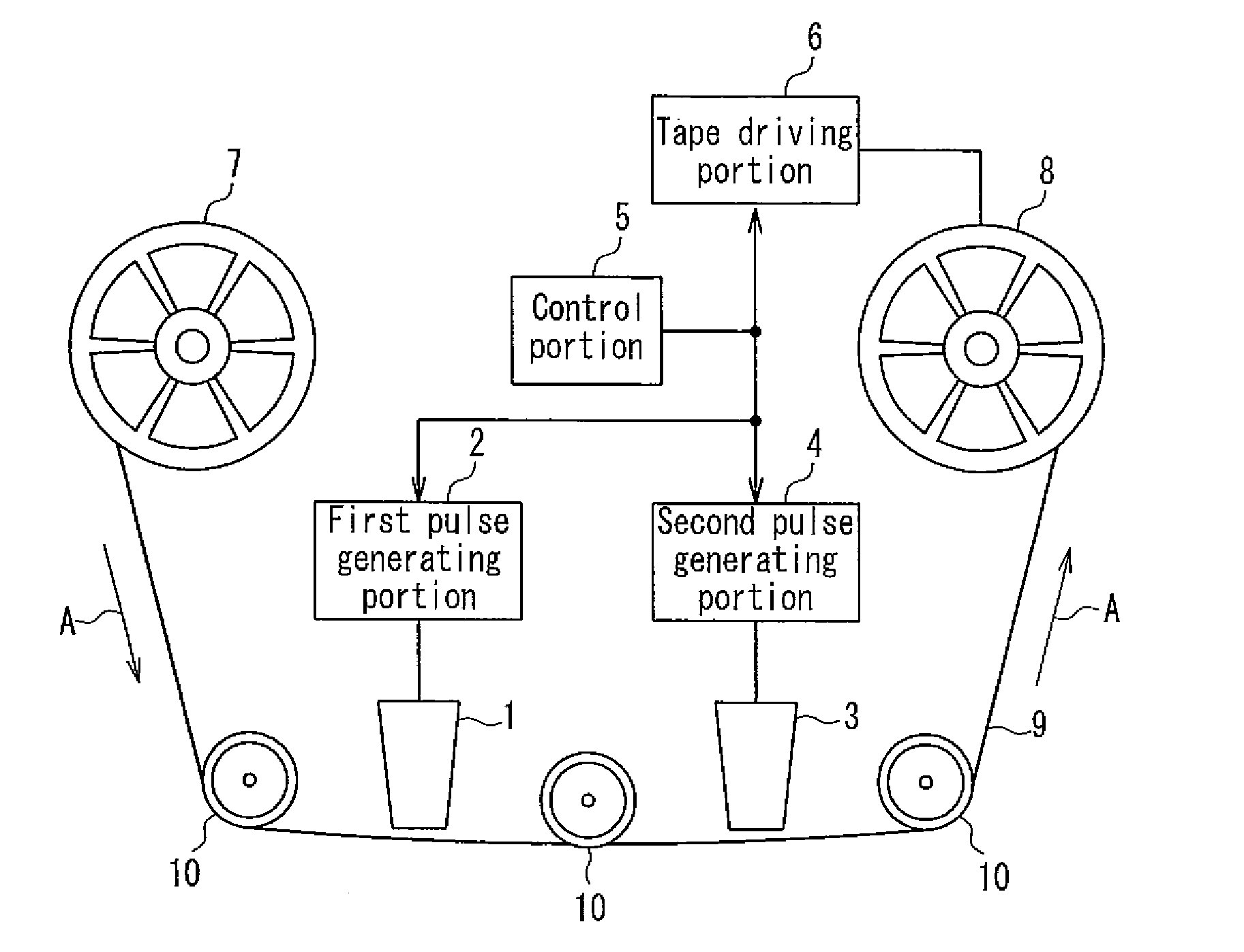
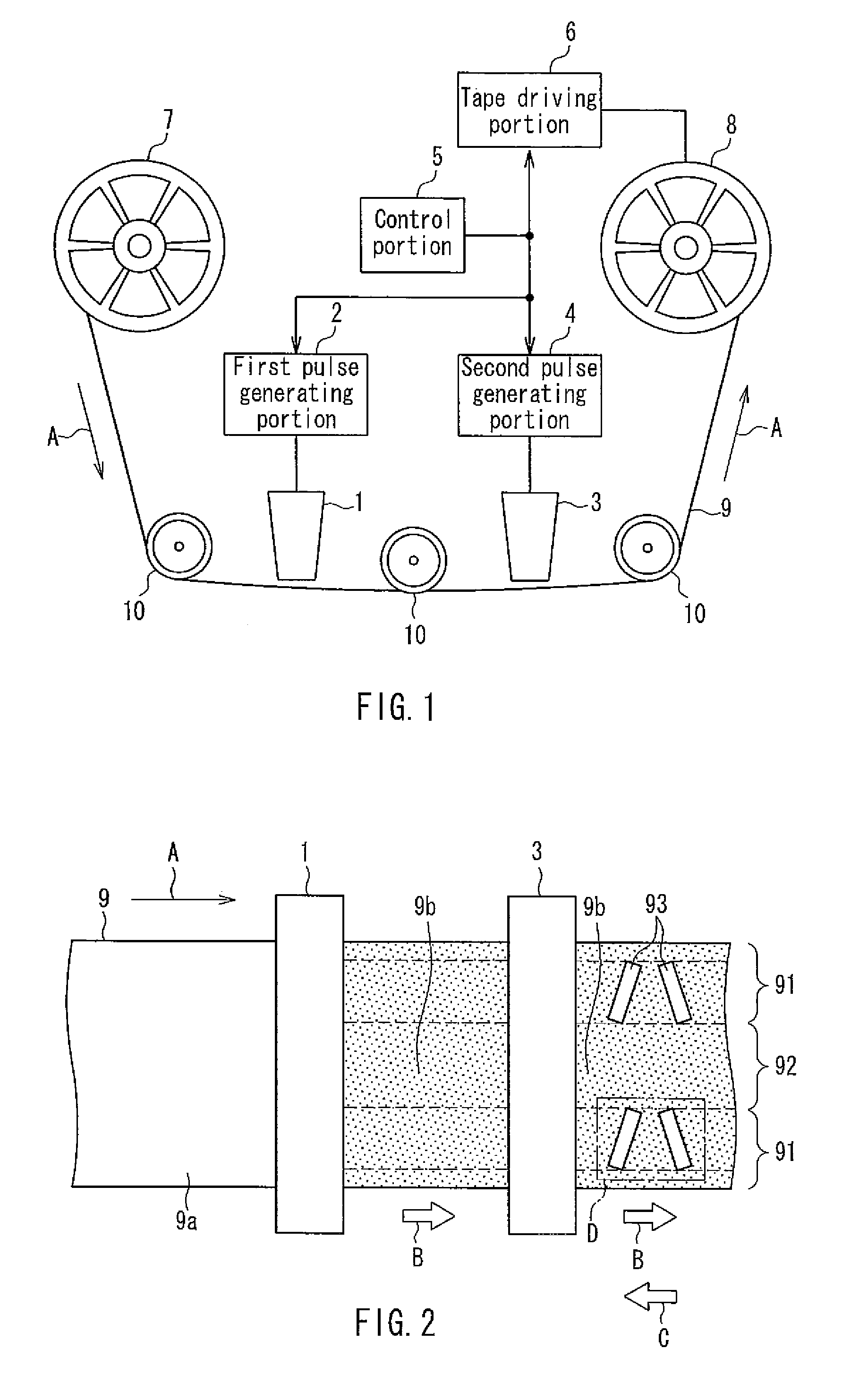
[0026]FIG. 1 is a schematic view of a servo signal recording apparatus according to Embodiment 1. As shown in FIG. 1, the servo signal recording apparatus includes an AC erasing head 1, a first pulse generating portion 2, a servo write head 3, a second pulse generating portion 4, a control portion 5, a tape driving portion 6, a first reel 7, a second reel 8, and guide rollers 10.

[0027]The AC erasing head 1 is operated based on a pulse generated by the first pulse generating portion 2 to AC-erase a magnetic layer of a magnetic tape 9. The AC erasing head 1 is an example of the AC erasing unit.

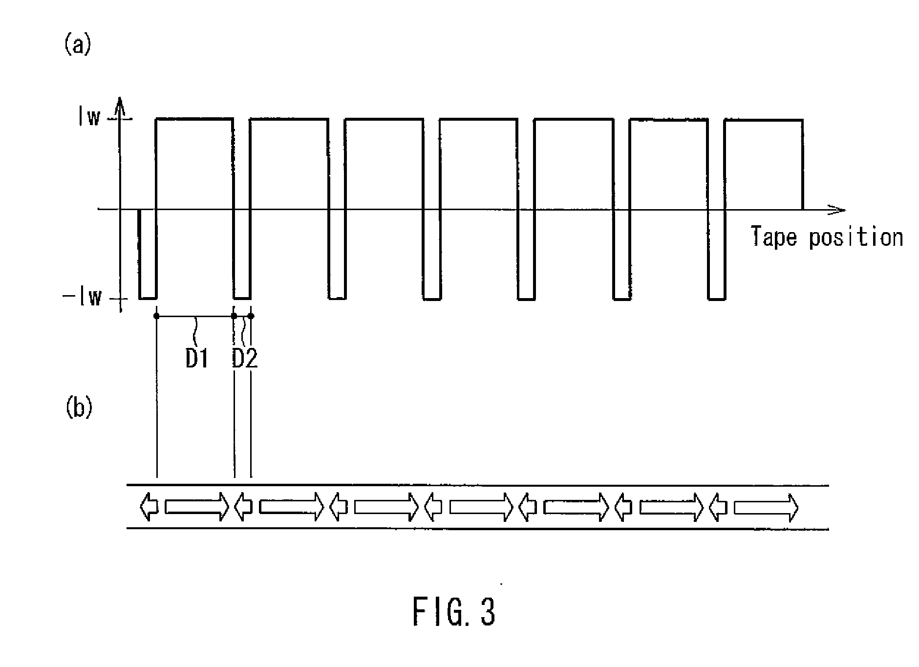
[0028]The first pulse generating portion 2 generates a pulse for operating the AC erasing head 1 by the control from the control portion 5. The pulse generated by the first pulse generating portion 2 has a predetermined duty ratio, and the duty ratio can be set to be an arbitrary value in the present embodiment.

[0029]The...


PUM

PropertyMeasurementUnit
magnetizationaaaaaaaaaa
residual magnetizationaaaaaaaaaa
magnetic fieldaaaaaaaaaa

Abstract

The present invention is a servo signal recording method for recording a servo signal on a magnetic tape having a data band and a servo band, wherein erasure is performed based on a pulse having a duty ratio varied so that a driving time of the AC erasing head with respect to one polarity is longer than a driving time thereof with respect to the other polarity, and then, the servo band is magnetized so as to have a magnetization direction opposite to magnetization direction caused by the erasure to record a servo signal in the servo band. According to this configuration, the influence of an information recording signal recorded on the surface of a magnetic recording medium on a reproduction output is reduced, whereby the reproduction output of a servo signal can be enhanced easily.

Description

BACKGROUND OF THE INVENTION[0001]1. Field of the Invention[0002]The present invention relates to a servo signal recording method for recording a servo signal on a magnetic recording medium having a servo band. The present invention also relates to a servo recording apparatus capable of recording a servo signal on a magnetic recording medium. The present invention also relates to a magnetic recording medium on which a servo signal is recorded by a servo signal recording method or a servo signal recording apparatus.[0003]2. Description of Related Art[0004]A magnetic tape that is a kind of magnetic recording medium finds various applications such as an audio tape, a video tape, and a computer tape. Particularly, in the field of a tape for a data backup in a computer, tapes with a storage capacity of hundreds of gigabytes per volume have been commercialized along with the increase in capacity of a hard disk in which a backup is to be created. In the future, the increase in capacity of a...

Claims


Application Information

Patent Timeline
Patent Type & Authority Applications(United States)
IPC IPC(8): G11B5/584G11B5/78
CPCG11B5/584
Inventor FUJITA, MASAOTANAKA, KENJIKAWARAI, SEIGI
Owner FUJIFILM CORP
Why Eureka
Try Eureka