Condenser Microphone

a condenser microphone and microphone technology, applied in the field of condenser microphones, can solve the problem of no prior art found, and achieve the effect of high responsiveness, increased output level, and resistance to circuit nois

Active Publication Date: 2011-09-15
AUDIO-TECHNICA
View PDF1 Cites 0 Cited by
  • Summary
  • Abstract
  • Description
  • Claims
  • Application Information

AI Technical Summary

Benefits of technology

[0023]In the condenser microphone having the transformer-free output circuit according to the present invention, the constant-voltage circuit is connected in series to the emitter terminal of the emitter-follower output circuit, and the operating voltage for the impedance converter is supplied from the constant-voltage circuit. The output level can thus be increased with a small output circuit without a large capacitor. In addition, the present invention provides a condenser microphone resistant to circuit noise and highly responsive to a low frequency.

Problems solved by technology

No prior art was found that has an object to solve the technical challenge described above, specifically to increase the maximum output level while maintaining the operating voltage for the impedance converter in the condenser microphone.

Method used


Image

  • Condenser Microphone
  • Condenser Microphone
  • Condenser Microphone

Examples


Embodiment Construction

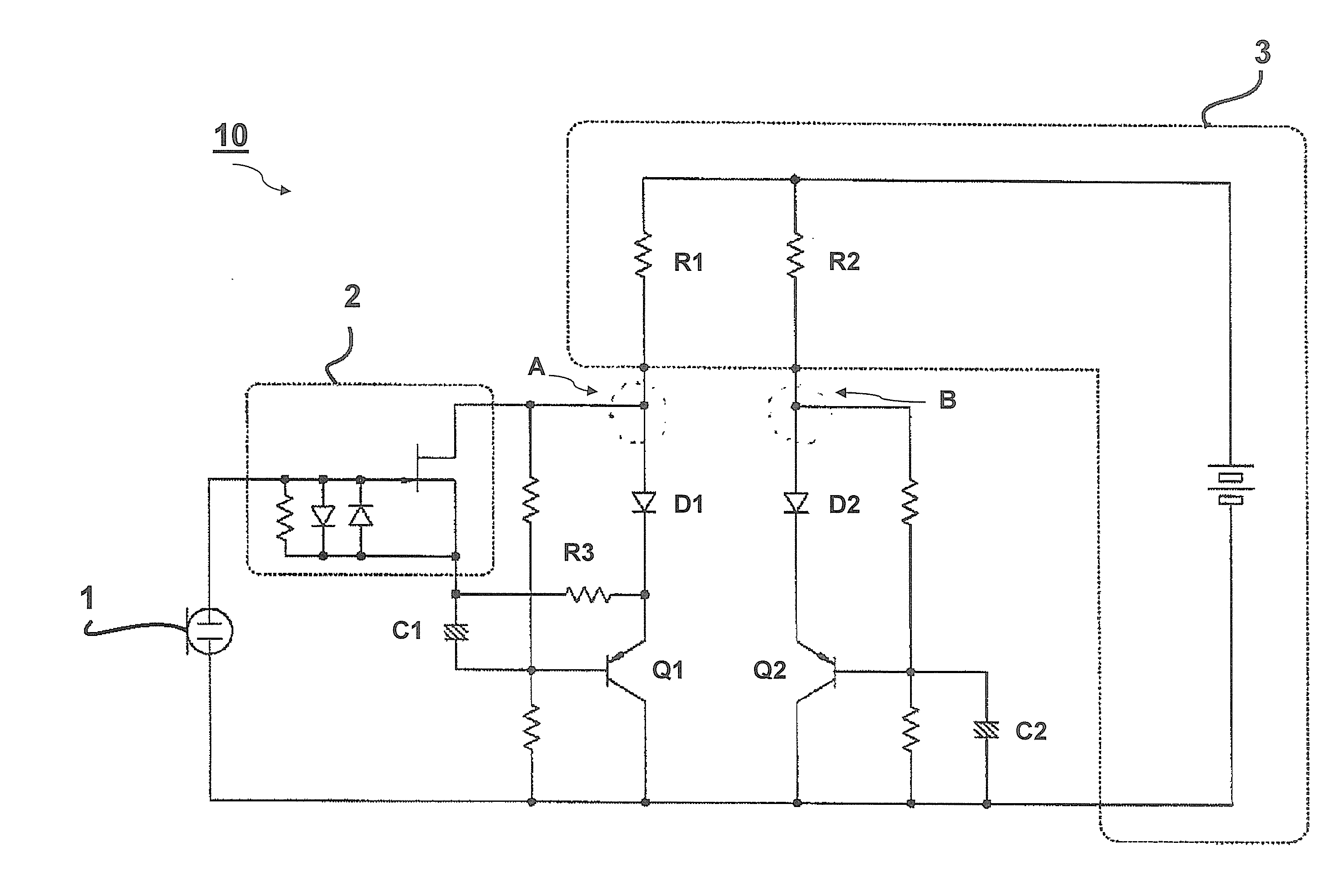
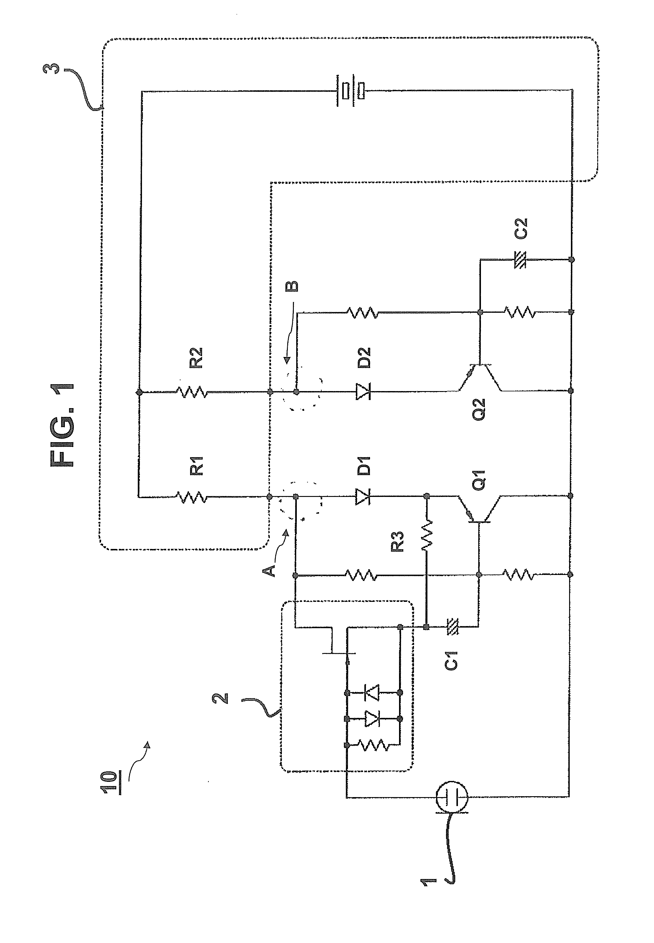
[0029]An embodiment of a condenser microphone according to the present invention is explained with reference to FIG. 1. In the drawing, an electret condenser microphone unit 1 has one end connected to an impedance converter 2 and the other end connected to a negative terminal of a phantom power source 3.

[0030]The positive terminal of the phantom power source 3 is connected to an emitter of a transistor Q1 through a supply resistor R1 and a diode D1, and to an emitter of a transistor Q2 through a supply resistor R2 and a diode D2. Thus, the supply resistors R1 and R2 also serve as load resistors for the emitter-follower connected transistors Q1 and Q2, respectively. The respective emitters of the transistors Q1 and Q2 are connected to output terminals (not shown in the drawing) in portions indicated by dotted line circles A and B, respectively. Audio signals converted by the microphone unit 1 are balance-output from the output terminals. For a voltage of the phantom power source 3 of...


PUM


Abstract

A condenser microphone has an output circuit comprising an emitter-follower circuit; an impedance converter comprising an FET and at least one transistor of the emitter-follower circuit provided next to the FET; and the transistor having an emitter terminal provided with a constant-voltage circuit. The FET included in the impedance converter is operated by a voltage supplied from the constant-voltage circuit.

Description

BACKGROUND OF THE INVENTION[0001]1. Field of the Invention[0002]The present invention relates to a condenser microphone having an emitter-follower output circuit that can increase the maximum output level without a transformer.[0003]2. Related Background Art[0004]Power supply systems for condenser microphones and other microphones are set forth in the EIAJ standard (RC-8162A). The EIAJ standard relates to a phantom power source and defines three types of supply voltages (12 V, 24 V, and 48 V). In the case where a phantom power source is used for a condenser microphone, the maximum amplitude of the output from the condenser microphone is thus 48 VP-P).[0005]In order to increase the output from the condenser microphone, a transformer may be provided in an output circuit thereof. If it is not suitable to include a transformer in the output circuit, a transformer-free output circuit is employed. An emitter-follower circuit is generally used in such a transformer-free output circuit in v...

Claims


Application Information

Patent Timeline
Patent Type & Authority Applications(United States)
IPC IPC(8): H04R11/04
CPCH04R19/04
Inventor AKINO, HIROSHI
Owner AUDIO-TECHNICA
Why Eureka
Try Eureka