Impedance conversion circuit of condenser microphone

a technology of condenser microphone and conversion circuit, which is applied in the direction of transducer details, electrical transducers, electrical apparatus, etc., to achieve the effect of wide dynamic range, increased negative feedback amount, and increased negative feedback amoun

Active Publication Date: 2017-05-30
AUDIO-TECHNICA
View PDF6 Cites 0 Cited by
  • Summary
  • Abstract
  • Description
  • Claims
  • Application Information

AI Technical Summary

Benefits of technology

[0019]The impedance conversion circuit illustrated in FIG. 3 can provide a larger feedback amount than the circuits disclosed in JP 3890301 B2 and JP 4426902 B2, which configure the PG feedback circuits in the voltage amplifier tube, and can secure a wide dynamic range according to the larger feedback amount.
[0021]An objective of the present invention is to provide, in an impedance conversion circuit of a condenser microphone using a grounded-cathode voltage amplifier circuit as an initial-stage input, an impedance conversion circuit of a condenser microphone, which can achieve a wide dynamic range and can increase a maximum output level and reduce a noise level, by providing a larger feedback amount to an electron tube of the initial-stage input.
[0029]Further, the feedback signal is transmitted from the first emitter-follower circuit having low output impedance to the grid of the first electron tube through the first feedback element, and thus the negative feedback amount can be increased. Accordingly, the impedance conversion circuit of a condenser microphone having a wide dynamic range using the voltage amplifier circuit can be provided.
[0030]In addition, a multi-feedback circuit that transmits the feedback signal from the second emitter-follower circuit to the cathode of the first electron tube through the second feedback element is configured, whereby the negative feedback amount can be further increased. Accordingly, the impedance conversion circuit of a condenser microphone can be provided which can achieve a wider dynamic range, increase of a maximum output level and reduction of a noise level.

Problems solved by technology

However, according to the impedance conversion circuit illustrated in FIG. 3, there is a technical drawback that the dynamic range is slightly narrower than the impedance conversion circuit of a condenser microphone using the field effect transistor, and obtaining a wider dynamic range is desired.

Method used


Image

  • Impedance conversion circuit of condenser microphone
  • Impedance conversion circuit of condenser microphone
  • Impedance conversion circuit of condenser microphone

Examples


Embodiment Construction

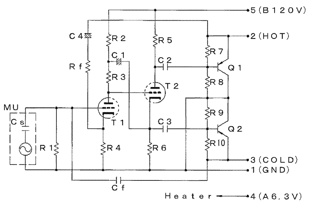
[0034]An impedance conversion circuit of a condenser microphone according to the present invention will be described with reference to FIG. 1.

[0035]Reference symbol MU represents a condenser microphone unit by an equivalent circuit. The condenser microphone unit is expressed such that a capacitor Cs is connected to a signal source in series. That is, the capacitor Cs corresponds to an electrostatic capacitance between a fixed electrode and a diaphragm that configure the condenser microphone unit, and its capacitance is about several tens of pF, as described above.

[0036]Then, one end of the condenser microphone unit MU is connected to a grid of a first electron tube T1, and the other end is connected to a terminal pin 1 of a connector as a ground line.

[0037]A grid leak resistor R1 is connected between the grid of the first electron tube T1 and the ground line. Further, a load resistor made of a series circuit of resistors R2 and R3 is connected to a plate of the first electron tube T...


PUM


Abstract

Provided is an impedance conversion circuit of a condenser microphone which includes a first electron tube operated in grounded-cathode mode to whose grid an output signal from a condenser microphone unit is inputted, and from whose plate a signal is outputted, a first emitter-follower circuit configured to receive a signal based on a plate output of the first electron tube and amplify a current, and a first feedback element configured to transmit a feedback signal from an emitter of a transistor configuring the first emitter-follower circuit to the grid of the first electron tube. And the impedance conversion circuit can achieve a wide dynamic range while using a voltage amplifier circuit with an electron tube at an initial stage.

Description

RELATED APPLICATIONS[0001]The present application is based on, and claims priority from, Japanese Application No. JP2015-197882 filed Oct. 5, 2015, the disclosure of which is hereby incorporated by reference herein in its entirety.BACKGROUND OF THE INVENTION[0002]Field of the Invention[0003]The present invention relates to an impedance conversion circuit of a condenser microphone using an electron tube (vacuum tube).[0004]Description of the Related Art[0005]A condenser microphone generates an audio signal based on change of an electrostatic capacitance between a diaphragm and a fixed electrode facing each other.[0006]That is, the condenser microphones in which the diaphragm is arranged to face the fixed electrode have an electrostatic capacitance of about several tens of pF and extremely high output impedance, and are thus configured to take out the audio signal through an impedance conversion circuit.[0007]An impedance conversion circuit with a field effect transistor (FET) or an e...

Claims


Application Information

Patent Timeline
Patent Type & Authority Patents(United States)
IPC IPC(8): H04R3/00H04R3/06
CPCH04R3/06
Inventor AKINO, HIROSHI
Owner AUDIO-TECHNICA
Why Eureka
Try Eureka