Screw for extruder, bearing segment used in the same and twin screw extruder provided with screw for extruder

a technology of screw and extruder, which is applied in the direction of mechanical equipment, mixing, and rigid support of bearing units, etc., can solve the problems of large kinetic load imposed on both a kneading segment and a rotor segment of the screw body, and achieves the effect of preventing bending, reducing the abrasion of the screw main body and the barrel, and reducing the kinetic load

Inactive Publication Date: 2008-07-31
KOBE STEEL LTD
View PDF59 Cites 8 Cited by
  • Summary
  • Abstract
  • Description
  • Claims
  • Application Information

AI Technical Summary

Benefits of technology

[0013]The present invention is achieved in consideration to the above problems and it is an object of the present invention to provide a screw for extruder capable of kneading a material to be kneaded by giving a large shear force, as well as preventing bending of a screw main body and suppressing abrasion of a flights and a barrel.
[0014]It is also an object of the present invention to provide a bearing segment capable of preventing movement of the screw main body.

Problems solved by technology

However, in the twin screw extruder in general, a large kinetic load is also imposed on a kneading screw as an adverse effect of a high kneading effect.
Particularly, a kinetic load imposed on both a kneading segment and a rotor segment of the screw body is very large.

Method used


Image

  • Screw for extruder, bearing segment used in the same and twin screw extruder provided with screw for extruder
  • Screw for extruder, bearing segment used in the same and twin screw extruder provided with screw for extruder
  • Screw for extruder, bearing segment used in the same and twin screw extruder provided with screw for extruder

Examples


first embodiment

[0068]FIG. 5 schematically shows a conventional screw for extruder 29 having no bearing segment 21 as well as FIG. 1. It should be noted that although the bearing segment 21 is not provided in the conventional screw for extruder 29, except for the above point, the same type of segments are provided in the same combination as in the screw for extruder 1 according to the

[0069]The abrasion amounts of the kneading disk segments 19 provided in A1 and A2 in FIG. 5A are 0.25% or more as shown in a1 and a2 in FIG. 5B. In segments other than A1 and A2 of the kneading portion 14, almost all the abrasion amounts are 0.05% or more. On the other hand, in segments in the feeding portion 13 and segments in the extruding portion 15, the abrasion amounts are low with 0.05% or less. Therefore, it is found that in the conventional screw for extruder 29, abrasion is generated at a position in the axial direction and the abrasion is easily generated particularly in the kneading portion.

[0070]FIG. 6 show...

second embodiment

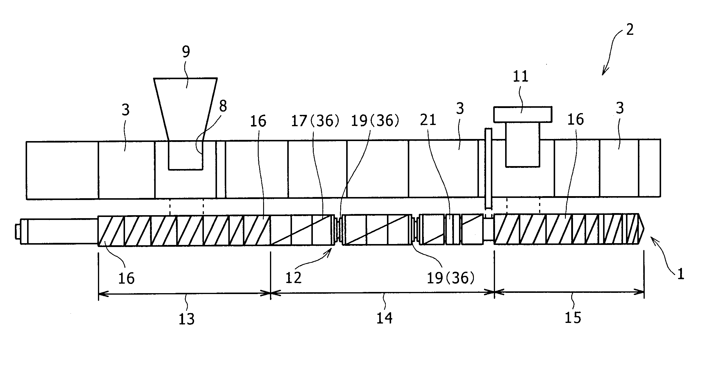
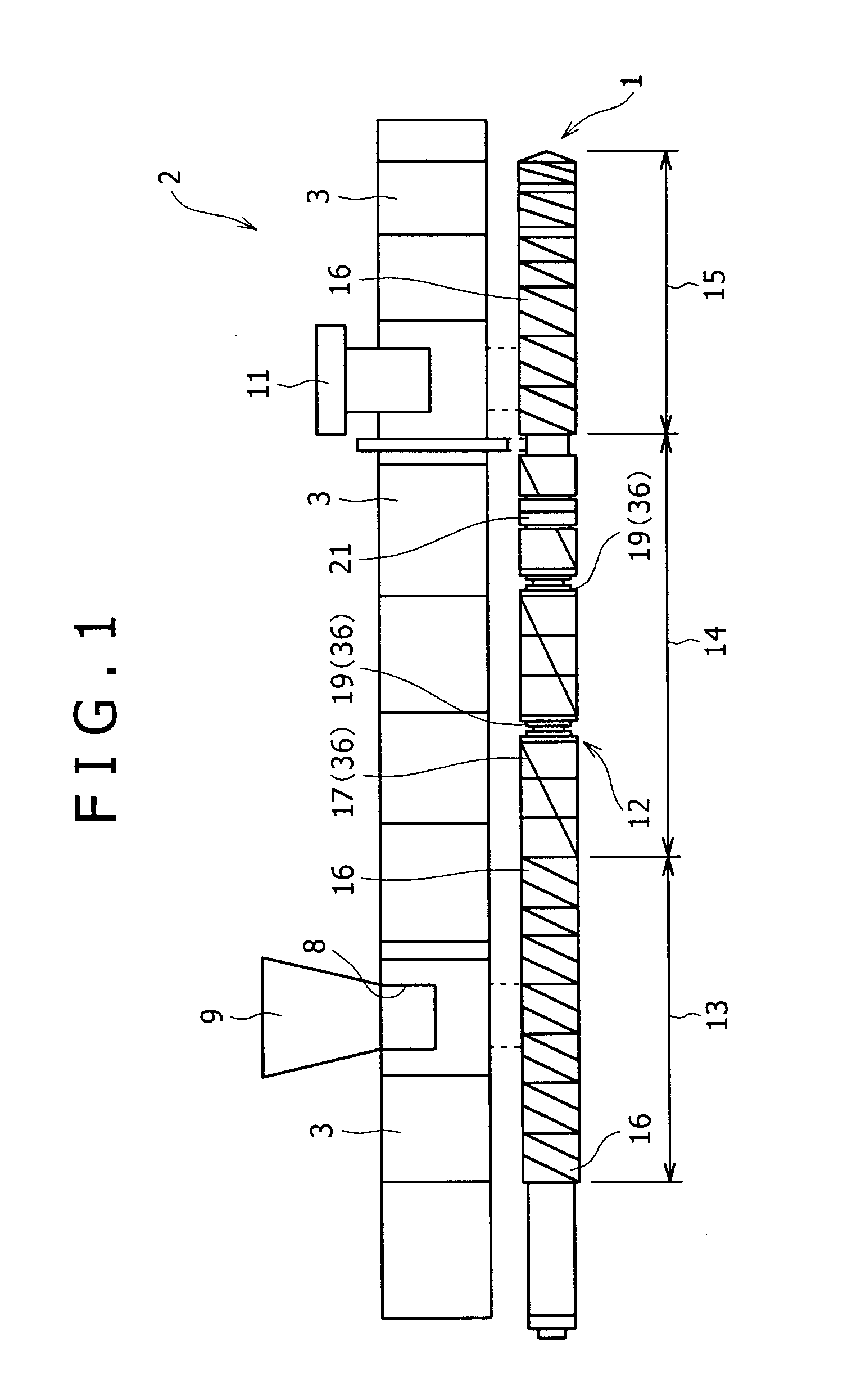
[0074]FIG. 7A shows the screw for extruder 1 of the In the screw for extruder 1, the bearing segment 21 is provided at a position where a distance S from an end of the downstream of the kneading portion 14 towards the downstream side thereof is 3.0 D or less (D: rotational outer diameter of the bearing segment), in the present embodiment, at a position where an end of the downstream of the bearing segment is on the downstream side at a distance of 3.0 D from the end of the downstream of the kneading portion 14.

[0075]In the screw for extruder 1 of the second embodiment, although the abrasion amounts of the kneading disk segments 19 shown in a1 and a2 in FIG. 7B are larger than the abrasion amounts of the first embodiment (the abrasion amounts of a1 and a2 in FIG. 6B), the abrasion amounts are smaller than the abrasion amounts of the conventional screw for extruder 29 (the abrasion amounts of a1 and a2 in FIG. 5B). In the abrasion amounts of the kneading disk segments 19 according to...

third embodiment

[0078]FIG. 8 shows the screw for extruder 1 of the The screw for extruder 1 has a second feeding portion 13b and a second kneading potion 14b following a first feeding portion 13a and a first kneading portion 14a, and the bearing segment 21 is provided at a position corresponding to the first kneading portion 14a.

[0079]In the screw for extruder 1 of the third embodiment, it is confirmed that the abrasion amounts of the kneading disk segments 19 of the first kneading portion 14a and the second kneading potion 14b are smaller than the abrasion amounts of a1 and a2 of the second embodiment. Therefore, as in the screw for extruder 1 of the present embodiment, in the case where a plurality of kneading portions 14 are provided in the axial direction of the screw main body 12 being apart from each other, it is determined as preferable that the bearing segment 21 is at least installed in the first kneading portion 14a located on the most upstream side among the plurality of kneading porti...


PUM

PropertyMeasurementUnit
angleaaaaaaaaaa
angleaaaaaaaaaa
lengthaaaaaaaaaa

Abstract

In a screw for extruder, a bearing segment having a function of supporting a screw main body at an intermediate part when kneading is performed is provided at a position corresponding to a kneading portion or on the downstream side of the kneading portion. The bearing segment is provided with at least two flights having a sectional shape of a complete meshing type with one streak in the axial direction, the flights are arranged in the rotational direction with uniformly displacing a phase thereof respectively, and length of the flights in the axial direction is set to 0.2D (D: rotational outer diameter of the bearing segment) or more. According to the above configuration, bending of the screw main body is prevented and abrasion of the flights and a barrel is suppressed.

Description

BACKGROUND OF THE INVENTION[0001]1. Field of the Invention[0002]The present invention relates to a screw for extruder provided with a bearing segment supporting a screw main body in order not to move the screw main body during kneading, the bearing segment used in the above screw for extruder, and a twin screw extruder provided with the above screw for extruder.[0003]2. Description of the Related Art[0004]In the case where a composite resin material is extruded, kneading is performed by adding a base material of a thermal plastic resin with an additive agent such as filler or a different synthetic resin. In such kneading, a continuous extruder is often used.[0005]A known continuous extruder is provided with a barrel having a long hollow portion (chamber) along the axial direction and a screw body passing through the hollow portion in the axial direction, and is a single screw extruder or a twin screw extruder in accordance with the number of the screw body.[0006]The continuous extru...

Claims


Application Information

Patent Timeline
Patent Type & Authority Applications(United States)
IPC IPC(8): B01F15/02F16C35/04B29C48/08B29C48/395B29C48/67
CPCB29C47/0021B29C47/60B29C47/402B29C47/38B29C48/08B29C48/395B29C48/402
Inventor YAMAGUCHI, KAZUOYAMANE, YASUAKIYOSHIMURA, SHOJI
Owner KOBE STEEL LTD
Why Eureka
Try Eureka