Method and apparatus for controlling output power levels of a laser used for optical data transmission based on data rate-speed optical feedback

a technology of optical data transmission and output power level, applied in the field of lasers, can solve the problems of limiting laser yield, difficult or impossible to determine the optimal adjustment of modulation current amplitude, and challenging to maintain optical power at a particular level

Inactive Publication Date: 2008-07-31
BROADCOM INT PTE LTD
View PDF4 Cites 13 Cited by
  • Summary
  • Abstract
  • Description
  • Claims
  • Application Information

AI Technical Summary

Benefits of technology

[0011]In accordance with the invention, high-speed measurements of the output power level of a laser are obtained by using a high-speed laser output power monitoring device that produces a high-speed electrical feedback signal. A high-speed amplitude detector receives the electrical feedback signal and detects the optical modulation amplitude (OMA) of the feedback signal and produces an OMA detection signal. The OMA detection signal is then received in a high-speed amplitude measurement device that measures the OMA and produces an OMA measurement value. The OMA measurement values is then processed by the laser controller to obtain a modulation current control signal, which is then output to the laser driver to cause the laser driver to adjust the laser modulation current to obtain a desired or optimum laser output power level.

Problems solved by technology

Due to the wide variations in laser parameters such as, for example, laser slope efficiency (SE) and laser threshold current (ITH), maintaining the optical power at a particular level is challenging because temperature and process variations and aging of system components also cause the output power level to vary.
A disadvantage of this technique is that using a single temperature reference point means the adjustment to the amplitude of the modulation current is essentially based on a “guess” of changes of the SE in direction and amount based on statistical or other data.
Because the change in the SE often is not linear and can change from positive to negative slope from one temperature to the next, it is difficult or impossible to determine the optimal adjustment in the amplitude of the modulation current.
In addition, this technique can also limit laser yields because the SE and ITH limits need to be within sufficiently tight tolerances to guarantee that a suitable level of performance will be achieved without the necessity of testing each laser over temperature and customizing each laser based on the results of testing.
One disadvantage of this technique is that it requires over-temperature testing during manufacturing, which is very time consuming and expensive.
In addition, it is difficult to factor in aging when using this technique, which means that the amplitude of the modulation current often will not be set to an optimal level.
A disadvantage of this technique is that it requires a large amount of signal processing to be performed to make the necessary calculations, and is therefore computationally intensive.
Another disadvantage is that the method is performed during module power up or module programming, and generally cannot be used while transmitting actual data.
In addition, this technique also requires a significant amount of signal processing, and is therefore computationally intensive.
This technique requires an additional high-bandwidth feedback path for the amplitude detector, which makes obtaining stable operation extremely difficult.
In addition, the performance of the amplitude detector can be significantly affected by temperature variations, which can lead to less than optimal performance.
Also, the amplitude detector dissipates a large amount of power relative to the rest of the transmitter due to its high bandwidth and continuous operation.
Because of these difficulties, this technique has been proposed, but not actually implemented.

Method used


Image

  • Method and apparatus for controlling output power levels of a laser used for optical data transmission based on data rate-speed optical feedback
  • Method and apparatus for controlling output power levels of a laser used for optical data transmission based on data rate-speed optical feedback
  • Method and apparatus for controlling output power levels of a laser used for optical data transmission based on data rate-speed optical feedback

Examples


Embodiment Construction

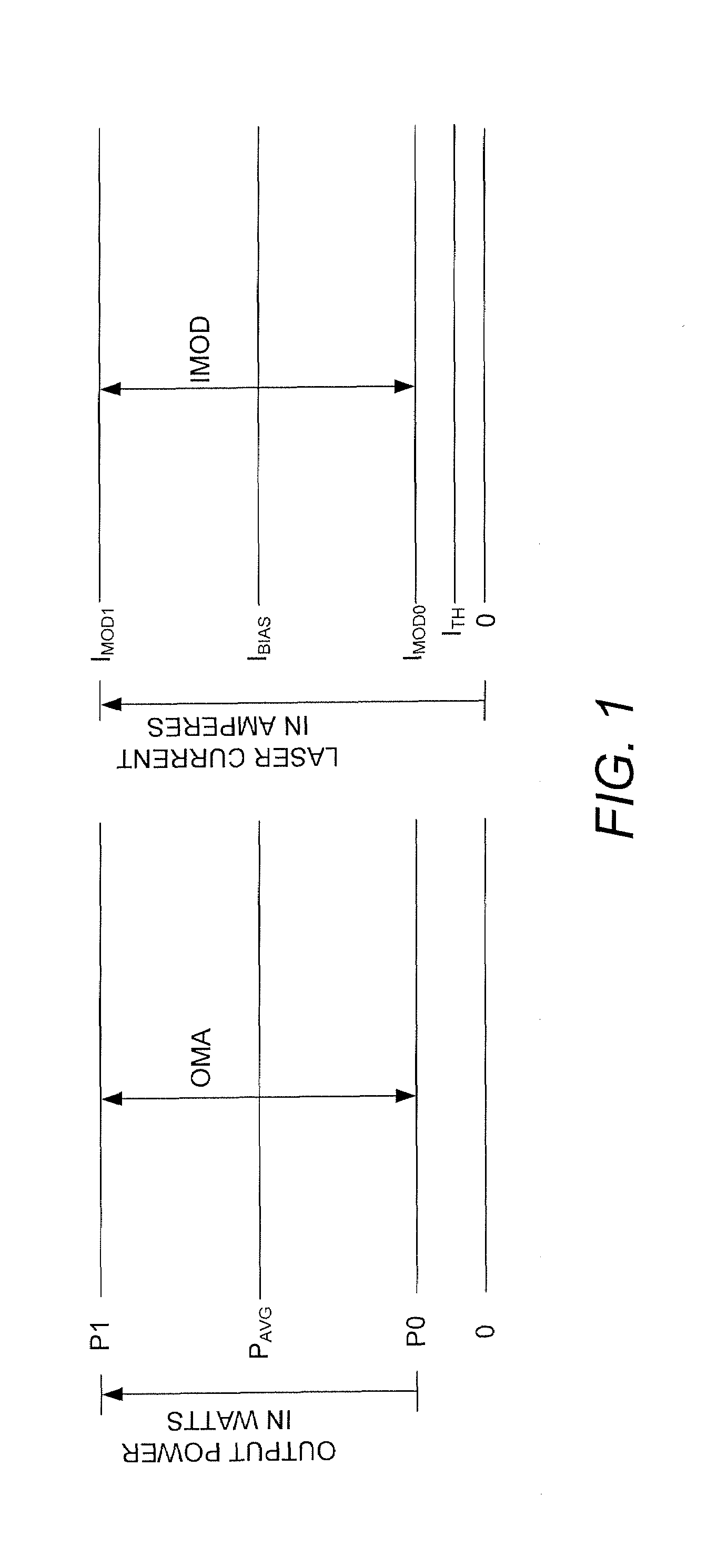
[0018]FIG. 1 illustrates a graph that demonstrates the relationship between laser output power in watts and laser current (bias, threshold and modulation) in amperes. To cause the laser to produce an output power level of P0 for a logic 0 level, the laser is modulated with a modulation current, IMOD0, that has an amplitude that is equal to or slightly greater than the amplitude of the laser threshold current, ITH. If the amplitude of IMOD0 falls below the amplitude of ITH, the laser is being over-modulated due to the fact that the laser is being turned off and the level of P0 cannot fall below zero, so the amplitude of the modulation current for a logic 1 level, IMOD1, must be increased in order to maintain IBIAS at a constant amplitude. Maintaining IBIAS at a constant amplitude generally results in the average output power level, PAVG, being maintained at a constant level, except when the laser is being over-modulated. When the amplitude of IMOD0 falls below the amplitude of ITH, t...


PUM


Abstract

High-speed measurements of the output power level of a laser are obtained by using a high-speed laser output power monitoring device that is capable of producing an electrical feedback signal having an amplitude that varies as the output power level of the laser varies. A high-speed amplitude detector receives the electrical feedback signal and detects the amplitude of the feedback signal and produces an optical modulation amplitude (OMA) detection signal. The OMA detection signal is received in a high-speed amplitude measurement device that measures the OMA and produces an OMA measurement value. The OMA measurement value is then processed by the laser controller to obtain a modulation current control signal, which is then output to the laser driver to cause the laser driver to adjust the laser modulation current to obtain a desired or optimum laser output power level. An average amplitude measurement value may also be obtained using an average amplitude measurement device that processes the OMA detection signal produced by the high-speed amplitude detector to obtain the average amplitude measurement value. The laser controller receives the average amplitude measurement value and processes it to obtain a bias current control signal, which is then output to the laser driver to cause it to adjust the amplitude of the bias current to obtain a desired or optimum average laser output power level.

Description

TECHNICAL FIELD OF THE INVENTION[0001]The invention relates to lasers. More particularly, the invention relates to controlling laser output power levels based on optical feedback signals that are fed back at the same speed as the rate at which data is being transmitted.BACKGROUND OF THE INVENTION[0002]Lasers are used in many different industries for many different purposes, such as, for example, in the medical industry for medical procedures, in the printing industry in laser printers, in the defense industry in a variety of defense applications, and in the optical communications industry for transmitting and receiving optical signals. In many applications, the output power of the laser is monitored and controlled to maintain the output power at a desired or required level. Due to the wide variations in laser parameters such as, for example, laser slope efficiency (SE) and laser threshold current (ITH), maintaining the optical power at a particular level is challenging because tempe...

Claims


Application Information

Patent Timeline
Patent Type & Authority Applications(United States)
IPC IPC(8): H01S3/00H01S3/02
CPCH01S5/0683H01S5/042
Inventor MILLER, FREDERICK W.
Owner BROADCOM INT PTE LTD
Why Eureka
Try Eureka