
Device and a method for operation of a high temperature fuel cell

a fuel cell and high temperature technology, applied in the direction of fuel cells, fuel cells, electrochemical generators, etc., can solve the problems of high demands on the control of the reformer (air/fuel ratio), the fluctuation of the fuel cell, and the li class, so as to achieve the effect of responding quickly

Inactive Publication Date: 2008-07-31
AVL LIST GMBH
View PDF11 Cites 8 Cited by
  • Summary
  • Abstract
  • Description
  • Claims
  • Application Information

AI Technical Summary

Benefits of technology

[0014]It is the object of the present invention to improve a device or a method for operating a high-temperature fuel cell using liquid fuel, and preferably diesel oil, in such a way that conventional pumping means for the gas streams may be employed, the system being able to respond quickly to load changes or fluctuations in reformate demand.
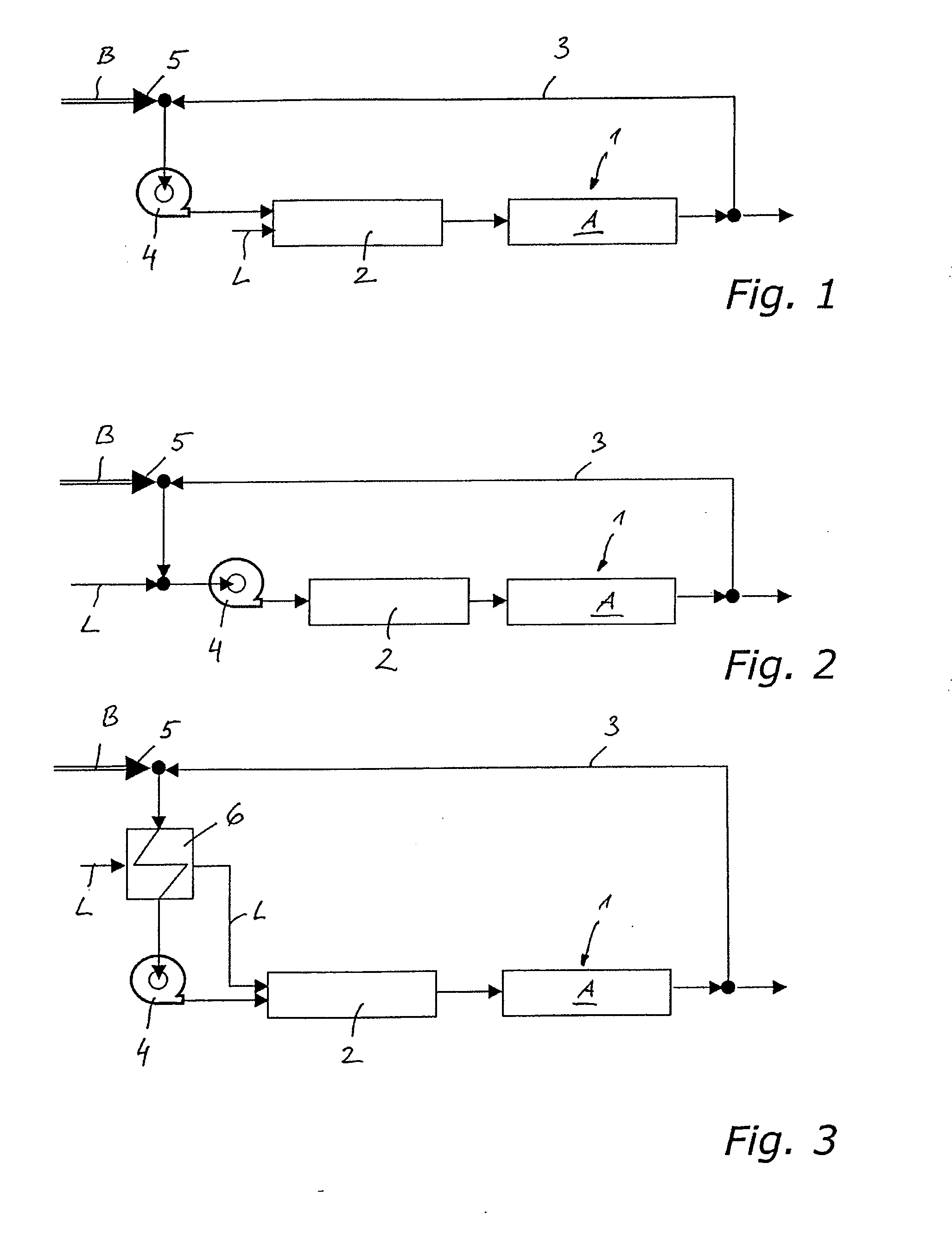
[0019]As an alternative to direct cooling by adding air, the mixture of anode exhaust gas and fuel may be cooled in a heat exchanger prior to entering the compressor, preferably with the help of the amount of air required for reforming the liquid fuel. This will avoid a large gas volume of ignitable mixture prior to reaction in the reformer.

Problems solved by technology

The following problems arise:Greatly fluctuating demand for reformed gas due to load changes of the fuel cell or the exhaust gas treatment unit will cause fluctuating pressure in the fuel cell and make high demands on reformer control (air / fuel ratio).Efficiency of pure partial oxidation in the reformer (i.e., without addition of water) is low.
If anode recirculation, as described in the above mentioned U.S. Pat. No. 5,208,114 A or in DE 103 15 697 A1 is used, the following disadvantages arise in the case of high-temperature fuel cells:Conventional pumps cannot be used to circulate hot gas streams.A jet pump (injector) as driver for the anode circuit demands very low pressure losses in the anode circuit and has insufficient load dynamics.

Method used


Image

  • Device and a method for operation of a high temperature fuel cell
  • Device and a method for operation of a high temperature fuel cell
  • Device and a method for operation of a high temperature fuel cell

Examples


Embodiment Construction

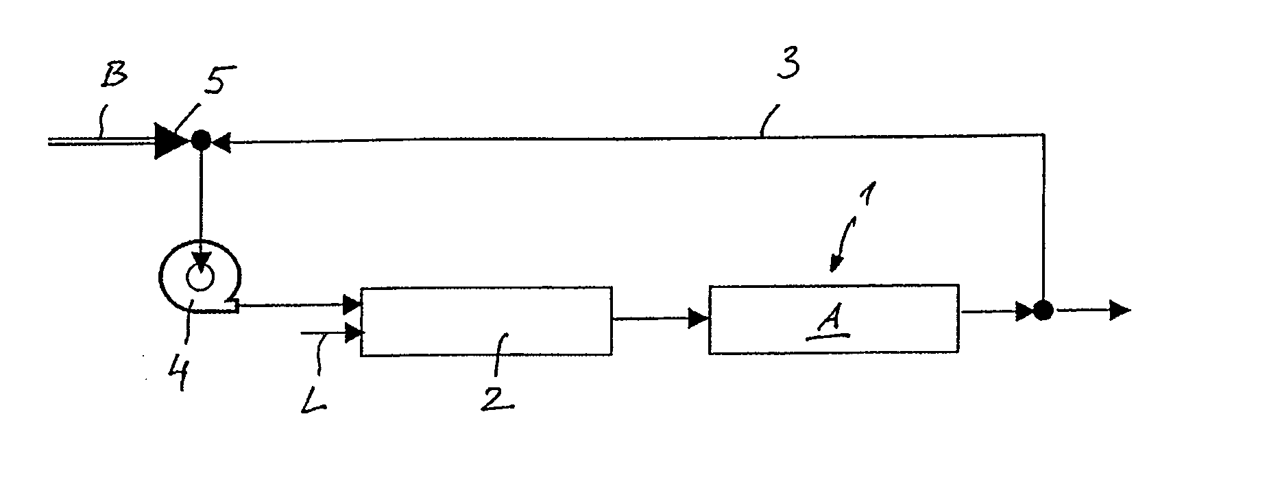
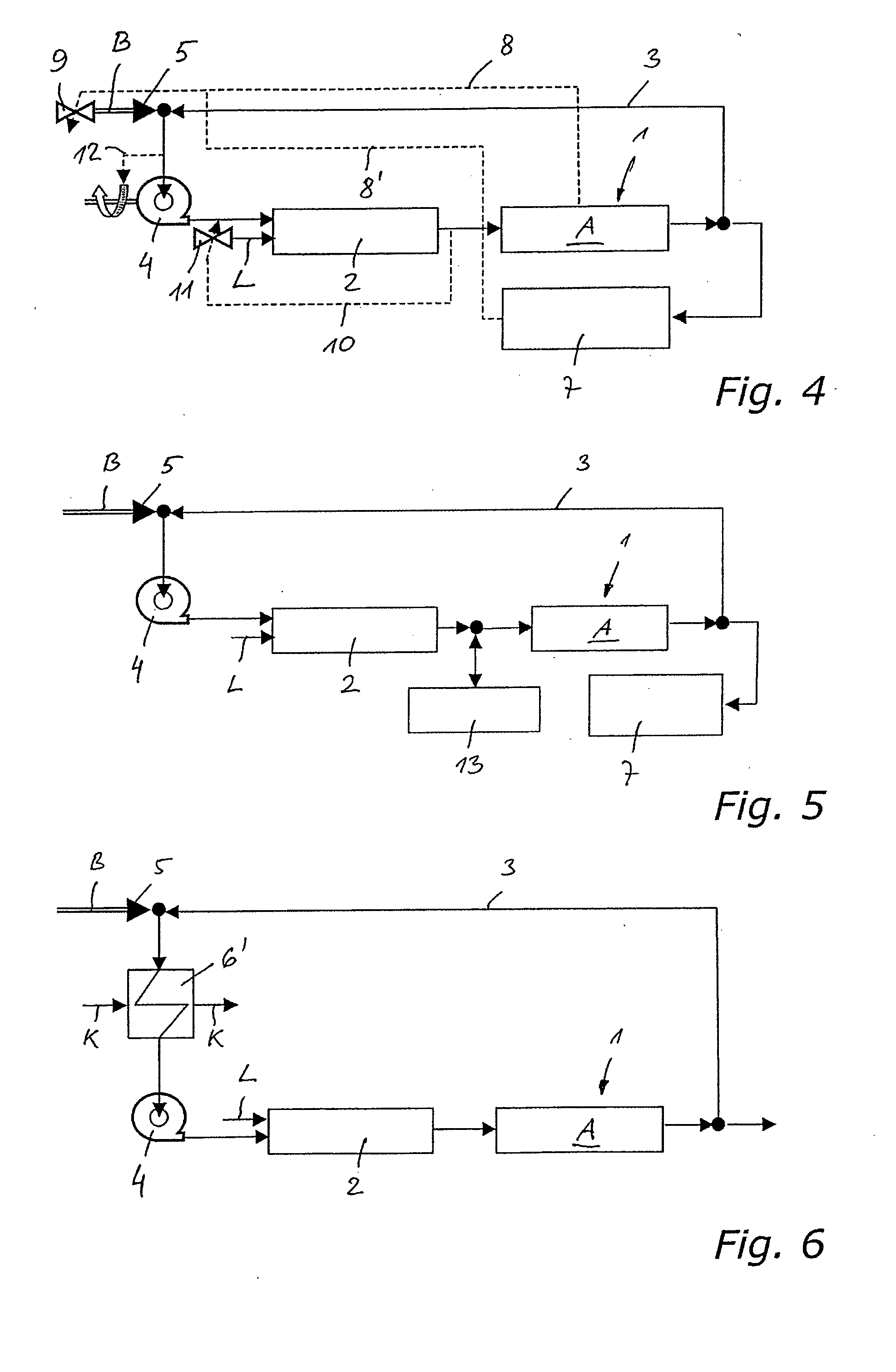
[0026]The device for operating a high-temperature fuel cell 1 with liquid fuel B, schematically shown in FIG. 1, has on the entry side of the anode A (the simplified drawing shows only anode A of the high-temperature fuel cell 1 or the fuel cell stack) a reformer 2 for the liquid fuel (liquid hydrocarbon, e.g., diesel oil). There is further provided a recirculation line 3 for the hot anode exhaust gas, which, departing from the exit side of the anode A of the high-temperature fuel cell 1, leads to the input side of the reformer 2. An injector 5 for injecting or spraying the liquid fuel B into the hot anode exhaust gas is located upstream of a compressor 4 preceding the reformer 2. The reformer 2 furthermore is provided with an inlet for the amount of air L required for reforming the fuel.

[0027]In the variant according to FIG. 2 the amount of air L required for reforming the liquid fuel is added to the mixture of anode exhaust gas and fuel upstream of the compressor 2.

[0028]In contra...


PUM


Abstract

The invention relates to a method and a device for operating a high-temperature fuel cell using liquid fuel, preferably diesel oil, where a reformer for the liquid fuel precedes the high-temperature fuel cell on the anode side. A recirculation line for the hot anode exhaust gas is provided, which departing from the outlet side of the anode of the high-temperature fuel cell leads to the inlet side of the reformer, an injector for spraying or injecting the liquid fuel into the hot anode exhaust gas being located upstream of a compressor preceding the reformer. The resulting cooling of the anode exhaust gas will permit the use of conventional positive displacement or rotary pumps in the anode circuit.

Description

BACKGROUND OF THE INVENTION[0001]The invention relates to a device and a method for operation of a high-temperature fuel cell, which operates on liquid fuel, preferably diesel oil, and which is preceded by a reformer for the liquid fuel on the anode side.[0002]High-temperature fuel cells using liquid fuel require an evaporation and reforming unit to convert the liquid fuel into a gaseous mixture which is suitable for the fuel cell.DESCRIPTION OF PRIOR ART[0003]From WO 2005 / 005027 A1, for instance, there is known a high-temperature fuel cell associated with an internal combustion engine, e.g., a solid oxide fuel cell (SOFC) or a molten carbonate fuel cell (MCFC), which operates on the liquid fuel of the combustion engine. According to an embodiment shown in FIG. 3 the high-temperature fuel cell is preceded by a reformer and possibly by a desulphurization device. The anode effluent is used in the exhaust treatment of the internal combustion engine and is fed into a high-temperature an...

Claims


Application Information

Patent Timeline
IPC IPC(8): H01M8/06H01M8/04
CPCH01M8/04007H01M8/04014H01M8/04097H01M8/04201H01M8/04373Y02E60/525H01M8/04753H01M8/04776H01M8/12H01M8/145Y02E60/521H01M8/04619Y02E60/50
Inventor RECHBERGER, JUERGENSCHUESSLER, MARTINPRENNINGER, PETER
Owner AVL LIST GMBH
Learn More