Clutch control device

a technology of clutch control and clutch plate, which is applied in the direction of fluid-actuated clutches, non-mechanical actuated clutches, clutches, etc., can solve the problem of not being able to obtain the same shift shock reducing effect in the initial condition, and achieve good shift shock reducing

Active Publication Date: 2008-07-31
HONDA MOTOR CO LTD
View PDF2 Cites 9 Cited by
  • Summary
  • Abstract
  • Description
  • Claims
  • Application Information

AI Technical Summary

Benefits of technology

[0008]It is accordingly an object of the present invention to provide a clutch control device which c

Problems solved by technology

Accordingly, when a clutch engagement point (meet point) becomes different from an initial position due to thermal expansion or wear of the clutch dis

Method used


Image

  • Clutch control device
  • Clutch control device
  • Clutch control device

Examples


Embodiment Construction

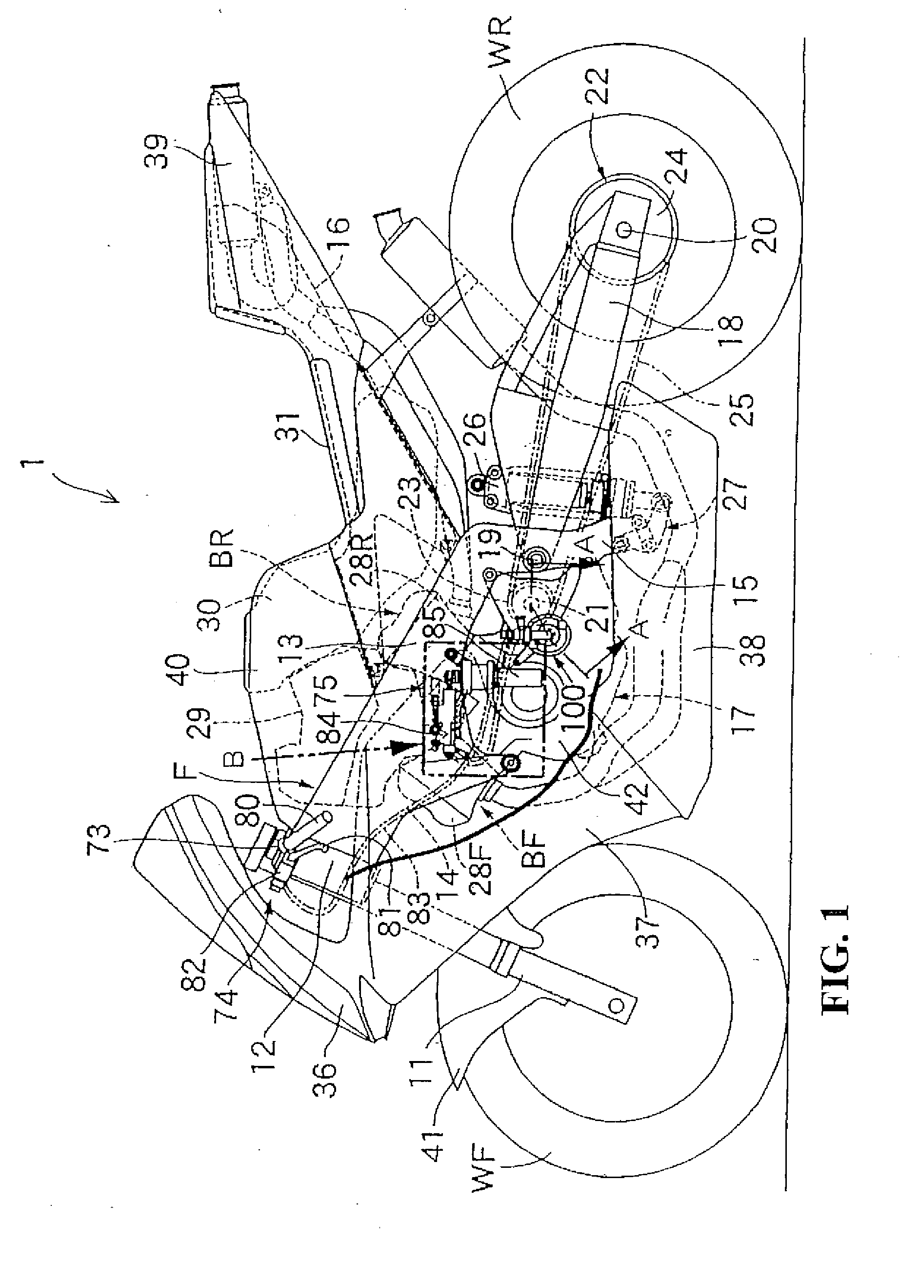
[0027]A preferred embodiment of the present invention will now be described in detail with reference to the drawings. FIG. 1 is a side view of a motorcycle adopting a clutch control device according to a preferred embodiment of the present invention. The motorcycle 1 has a body frame F, which includes a head pipe 12 for steerably supporting a front fork 11 for rotatably supporting a front wheel WF, a pair of right and left main frames 13 extending rearwardly from the head pipe 12 so as to be inclined downwardly, a pair of right and left engine hangers 14 welded to the head pipe 12 and the front portions of the right and left main frames 13 and extending downwardly ftrom the main frames 13, a pair of right and left pivot plates 15 extending downwardly from the rear portions of the right and left main frames 13, and a rear frame 16 connected to the rear portions of the main frames 13 and extending rearwardly therefrom so as to be inclined upward.

[0028]A V-type engine 17 (e.g., V-type ...


PUM


Abstract

A clutch control device for obtaining a good shift shock reducing effect regardless of a change in clutch engagement point. A target NeV database stores a target NeV map as a target value of the ratio between an engine speed (Ne) and a vehicle speed (V) obtained from the engine speed after primary speed reduction by a gear transmission. The time period from the time of detection of a downshift operation to the time of completion of the reengagement of the clutch is composed of a first period until the clutch becomes a partially engaged condition after disengagement of the clutch, a second period during which the partially engaged condition is maintained, and a third period from the time when the clutch in the partially engaged condition starts to be driven in its engaging direction to the time when the reengagement of the clutch is completed.

Description

CROSS-REFERENCE TO RELATED APPLICATIONS[0001]The present application claims priority under 35 USC 119 to Japanese Patent Application No. 2007-019247 filed on Jan. 30, 2007 the entire contents of which are hereby incorporated by reference.BACKGROUND OF THE INVENTION[0002]1. Field of the Invention[0003]The present invention relates to a clutch control device, and more particularly to a clutch control device which can always obtain a good shift shock reducing effect regardless of a change in clutch engagement point.[0004]2. Description of Background Art[0005]An automatic clutch device is known wherein a clutch for connecting and disconnecting the transmission of a drive force between an engine and a transmission is driven by an actuator[0006]Japanese Patent Laid-Open No. 2003-294062 discloses a control method for a clutch in the case of disengaging the clutch by driving an actuator, next performing a downshift operation, and next reengaging the clutch by driving the actuator, wherein a...

Claims


Application Information

Patent Timeline
IPC IPC(8): B60W10/02
CPCF16D25/086Y10T477/6418F16D48/04F16D48/066F16D48/068F16D2048/0254F16D2500/1024F16D2500/3024F16D2500/3067F16D2500/3108F16D2500/50684F16D2500/70412F16D2500/70426Y10T477/753F16D29/005
Inventor KOBAYASHI, FUYUKIMUROHASHI, KOHSAKUKUNIKIYO, KATSUHIRO
Owner HONDA MOTOR CO LTD
Why Eureka
Try Eureka