Orthopedic screw insert

a screw and insert technology, applied in the field of screw inserts, can solve the problems of compromising the limited anchoring strength of bone screws, and limited anchoring strength, and achieve the effect of promoting insert flexur

Active Publication Date: 2008-07-31
NUVASIVE
View PDF37 Cites 66 Cited by
  • Summary
  • Abstract
  • Description
  • Claims
  • Application Information

AI Technical Summary

Benefits of technology

[0009]The subject invention is directed to a new and useful insert for receiving a bone screw. The insert includes an elongate sleeve having opposed proximal and distal ends. A wall of the sleeve is defined by an outer peripheral surface configured for engaging bone and an inner peripheral surface configured for receiving a bo...

Problems solved by technology

The anchoring strength of bone screws as described above is limited.
Anchoring strength can be limited by defects in the bone.
Errors in the placement of the bore can also compromise the anchoring strength of bone screws.
This is a significant limitation for spinal devices, especially those aimed at non-fusion applications such as dynamic stabilization devices.
Placement and insertion of bores and screws is often difficult in bony structures such as the pedicle or facet.
An alignment mistake can lead to the bore lying too close to or breaking through the cortex on one side of the bone structure.
When a bone is compromised in this manner, it may provide inadequate load distribution for use of a conventional bone screw.

Method used


Image

  • Orthopedic screw insert
  • Orthopedic screw insert
  • Orthopedic screw insert

Examples


Embodiment Construction

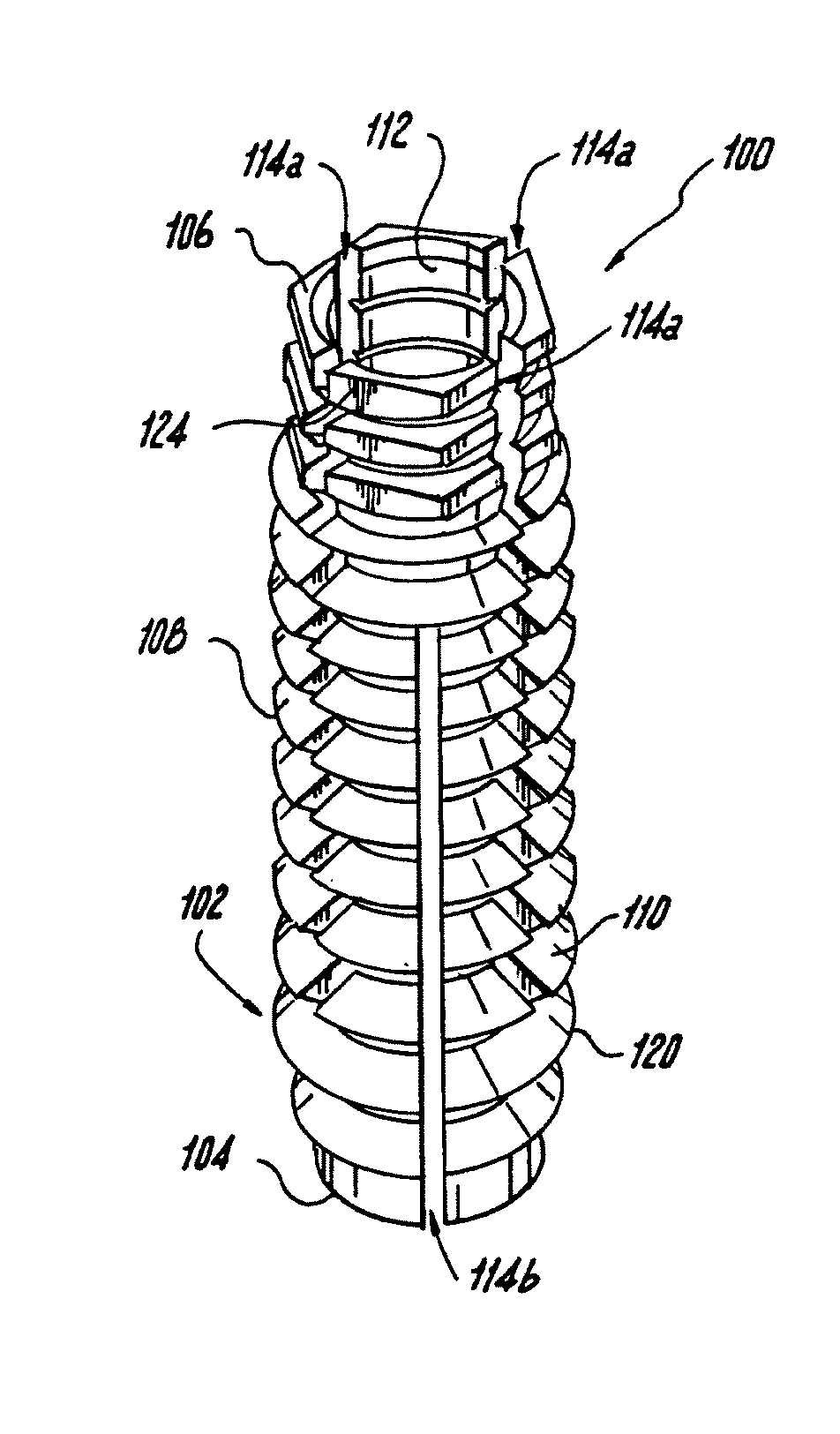
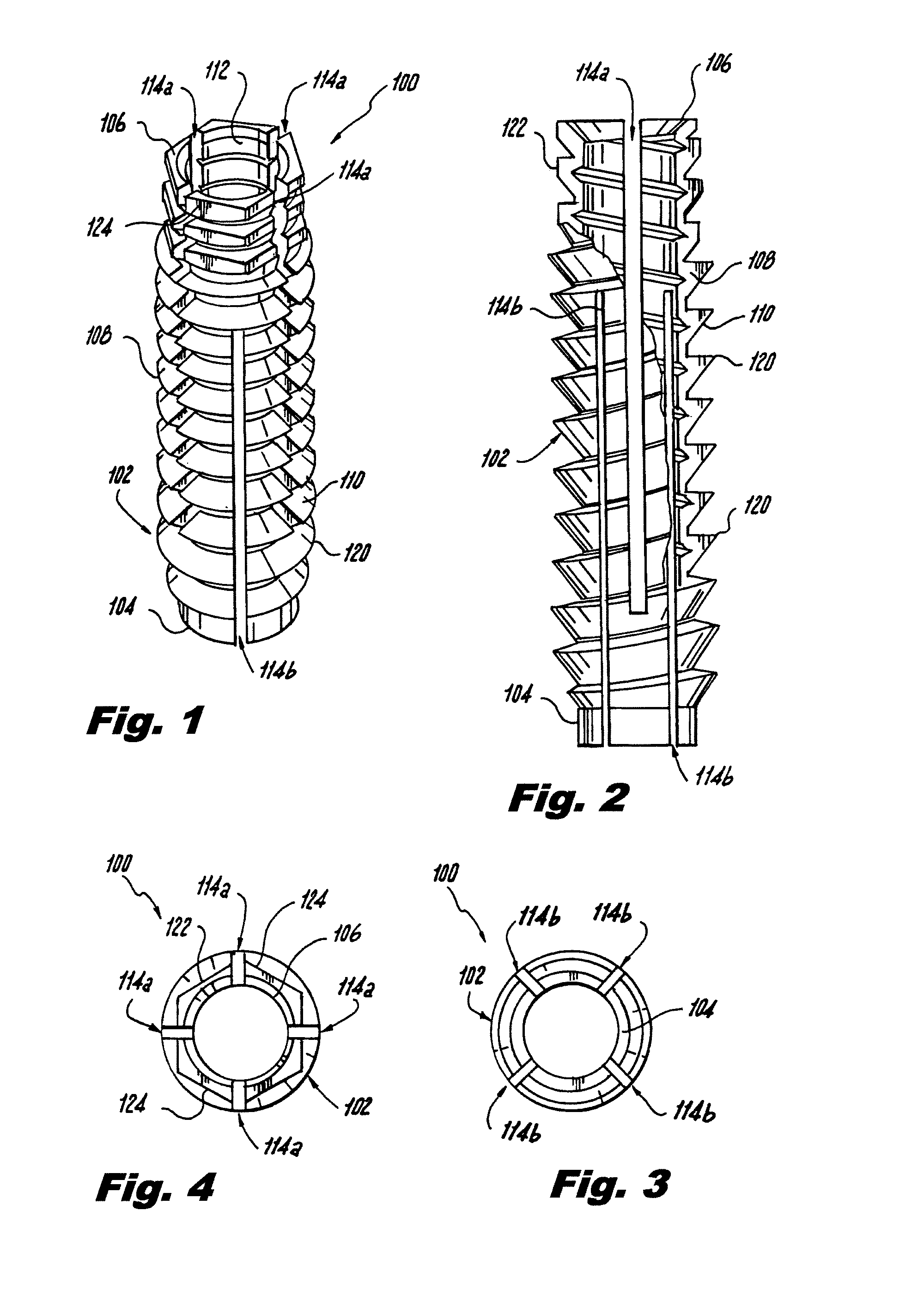
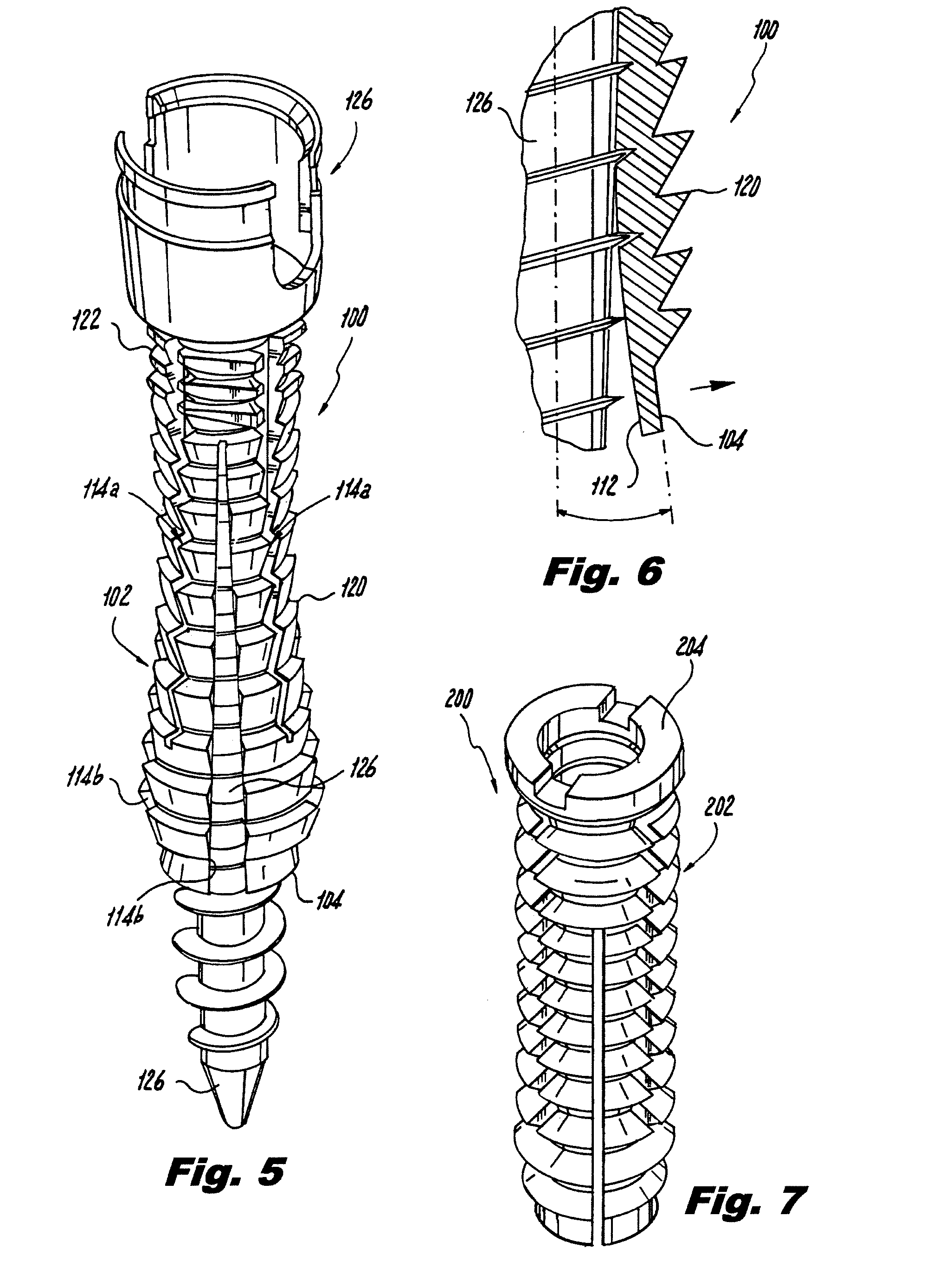
[0033]Referring now to the drawings, wherein like reference numerals identify or otherwise refer to similar structural features or elements of the various embodiments of the subject invention, there is illustrated in FIG. 1 an insert for receiving a bone screw designated generally by reference character 100.

[0034]As depicted in FIGS. 1 and 2, insert 100 includes a sleeve 102 with a distal end 104 and a proximal end 106. A wall 108 of sleeve 102 is defined between outer peripheral surface 110 and inner peripheral surface 112. Elongate slots 114a, 114b are defined through the thickness of wall 108 from outer peripheral surface 110 to inner peripheral surface 112.

[0035]Slot 114a is a proximal slot extending from proximal end 106 of sleeve 102, through a middle portion of the sleeve, and ending proximal from distal end 104 of sleeve 102. Slot 114b, on the other hand, is a distal slot that extends from distal end 104, through a middle portion of the sleeve, and ends short of proximal end...


PUM


Abstract

An insert for receiving a bone screw includes an elongate sleeve having opposed proximal and distal ends and a wall defined by an outer peripheral surface configured for engaging bone and an inner peripheral surface configured for receiving a bone screw extended therethrough. At least one elongate slot is formed in the wall of the sleeve for promoting flexure of the insert. A tool for affixing an orthopedic screw insert within bone tissue includes a socket portion configured and adapted to engage a proximal section of an outer peripheral surface of an orthopedic screw insert. A driver extends distally from the socket portion. The driver is configured and adapted to engage a section of an inner peripheral surface of the orthopedic screw insert distal from the socket portion.

Description

CROSS-REFERENCE TO RELATED APPLICATION[0001]This application claims the benefit of priority from U.S. Provisional Patent Application Ser. No. 60 / 881,110, filed Jan. 19, 2007, the disclosure of which is incorporated by reference herein in its entirety.BACKGROUND OF THE INVENTION[0002]1. Field of the Invention[0003]The present invention relates to a screw insert, and more particularly, to an insert for receiving a bone screw to increase the anchoring strength of the bone screw.[0004]2. Description of Related Art[0005]A variety of devices are known in the art for anchoring surgical components to bones. Of such devices, many are directed to bone screws for attaching bones together or to attaching prostheses to bones. There are several uses for bone screws in treating spinal conditions, treating joints, and anchoring sutures to bones, among others.[0006]Typically, when a bone screw is implemented to treat a bone condition, a drill is used to bore into the bone. The resulting bore typical...

Claims


Application Information

Patent Timeline
IPC IPC(8): A61B17/56
CPCA61B17/686
Inventor GLAZER, PAUL A.JORDAN, ROBERTHAROUTUNIAN, JOHN
Owner NUVASIVE
Why Eureka
Try Eureka